Nuclear Power Plant and a Steam Turbine

a nuclear power plant and steam turbine technology, applied in steam engine plants, reactor fuel elements, lighting and heating apparatus, etc., can solve the problems of high chemical activity, high cost of technical measures, and the inability to restore the full capacity of the plant for a short time, so as to facilitate the operation and facilitate the adjustment of capacity. , the effect of quick loading

Inactive Publication Date: 2008-08-21
KUDRYAVTSEV MIKHAIL YURIEVICH
View PDF7 Cites 4 Cited by
  • Summary
  • Abstract
  • Description
  • Claims
  • Application Information

AI Technical Summary

Benefits of technology

[0015]Gas turbines are easier started at any temperature and more quickly accept loading, than steam turbines. Besides unlike steam turbines at gas ones it is easier to adjust capacity by change of pressure of a working medium with preservation of high heat efficiency in a wide interval of loadings. Therefore in described nuclear power plant the use of the gas turbines for a drive of pumps, for example supplying pumps of steam turbines, increases heat efficiency of plant at frequent reduction of used capacity, for example at nights. This heat efficiency increases as due to higher heat efficiency at low power of gas turbines on comparison with steam ones, and due to faster acceptance of loading by the pumps, reducing duration of the start-up of steam turbines up to the size, allowing to stop for the night a part of steam turbines and to use the remained part on higher capacity corresponding higher heat efficiency.
[0016]Additional intermediate steam heating during steam expansion in the turbine by supplying the gas after gas turbines into the channels embodied in the directing device of the steam turbine and / or in driving wheels of the steam turbine also increases heat efficiency of described nuclear power plant. The additional intermediate steam heating is the most effective at pass of the heating medium through channels in a direction of a steam course.
[0017]The warming up of steam turbines by means of the gaseous heat-carrier, which is passing through channels for the heating medium, with the minimal expenses supports the stopped steam turbines in a hot condition. The hot condition reduces duration of start-up of steam turbines up to the size, allowing to stop for the night a part of steam turbines and to use the remained part on higher capacity that corresponding higher heat efficiency.

Problems solved by technology

Lack of this plant at use of sodium as liquid metal is high chemical activity of sodium to the water.
Such activity demands expensive technical measures to prevent the emergency contact of sodium with water at loss of tightness of heat exchangers and to reduce the consequences of formation of gaseous hydrogen in explosive concentration.
However in the plant described above the admissible duration of frequent start-up of steam turbines from the stopped condition does not allow the restoring of full capacity of plant for short time, for example, at transition from a night minimum to a morning maximum of power consumption.
That considerably reduces heat efficiency at the minimal used capacity.
However the use in this plant mixing heat exchangers >, polluting the gas by vapor of metal, does not allow to use heat energy of gas in power plants to increase the heat efficiency of plant.

Method used


Image

  • Nuclear Power Plant and a Steam Turbine
  • Nuclear Power Plant and a Steam Turbine

Examples


Embodiment Construction

[0028]The described group of inventions can be carried out as follows.

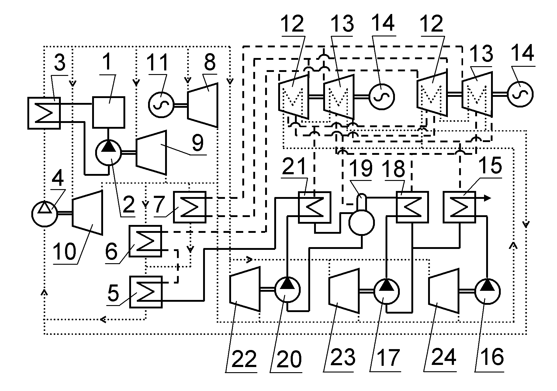
[0029]In a nuclear reactor (1) liquid metal, for example lead, heats up to temperature 830 K. In not-mixing heat exchanger (3) > this metal is cooled up to 670 K and again is moved into a reactor (1) by pump (2). Heat of this metal in heat exchanger (3) > heats the gas, for example, nitrogen, from temperature 620 K up to 790 K. Heated nitrogen goes into gas turbine unit with the closed cycle without heat recovery, and after use in gas turbines (8, 9, 10, 22, 23, 24) nitrogen gets temperature 580 K. In not-mixing heat exchangers (5, 6, 7) > nitrogen is cooled up to 460 K, giving heat to the water evaporated at pressure 5.5 MPa. The cooled nitrogen is compressed by compressor (4) up to a degree of compression p=3, corresponding to temperature 620 K, and moves into heat exchanger (3) >.

[0030]Produced in heat exchangers (5, 6) “gas-water” steam with pressure 5.5 MPa and temperature 540 K moves into steam turbines (ste...


PUM


Abstract

The group of inventions relates to nuclear techniques and to power industry.
The nuclear power plant contains a nuclear reactor (1) cooled by liquid metal, for example lead. Heated-up liquid metal is cooling in heat exchanger <<liquid metal-gas>> (3). This heat exchanger is embodied as not-mixing heat exchanger. The pump (2) moves cooled liquid metal through the filters into the reactor (1). The compressor (4) moves gas through heat exchanger <<liquid metal-gas>> (3) into gas turbines (8, 9, 10, 22, 23, 24). After gas turbines this gas vaporizes and overheats the water in heat exchangers <<gas-water>> (5, 6, 7) and moves back to compressor (3). Produced steam moves the steam turbines (12, 13), condenses into the water by means of condenser (15) and circulation pump (16) and then is moved by the pumps (17, 20) back to heat exchangers <<gas-water>> (5, 6, 7). At least one of gas turbines (22, 23, 24) is coupled by shaft with at least one of said pumps (16, 17, 20), and in steam turbines (12, 13) the channels are embodied for the heating medium. Said channels are embodied in the directing device of the steam turbine (12, 13) and/or in driving wheels of the steam turbine (12, 13). Said channels are series connected among them in a direction of a steam course in the turbine (12, 13). The gas after gas turbines (8, 9, 10, 22, 23, 24) is used besides heat exchangers (5, 6, 7) as said heating medium and after that moves into compressor (3). The nitrogen, air, helium, carbon dioxide or their mix are used as said gas.
Said group of inventions makes it possible to increase the heat efficiency of nuclear power plant with a reactor cooled by liquid metal at least up to 50% and to preserve high heat efficiency of this plant at frequent multiple reduction of used capacity of this plant, for example at nights.

Description

FIELD OF THE INVENTION[0001]The group of inventions relates to nuclear techniques and to power industry.PRIOR ART[0002]The nuclear power plant is known that includes a nuclear reactor cooled by the liquid metal, not-mixing heat exchangers for evaporation of water by means of this metal and the steam turbines moved by received steam. At that sodium is used as liquid metal (see patent SU 319142, F 01 K 27 / 00, 28.10.1971).[0003]Lack of this plant at use of sodium as liquid metal is high chemical activity of sodium to the water. Such activity demands expensive technical measures to prevent the emergency contact of sodium with water at loss of tightness of heat exchangers and to reduce the consequences of formation of gaseous hydrogen in explosive concentration. Heat efficiency of this plant (the factor of transformation of a nuclear reactor heat into energy of rotation of turbines) does not exceed 44% and depends on capacity at which plant is used. For preservation the heat efficiency a...

Claims


Application Information

Patent Timeline
Patent Type & Authority Applications(United States)
IPC IPC(8): G21D5/08G21C15/00
CPCF01K3/181F22B1/063Y02E30/34G21Y2002/201G21Y2004/30G21C1/02Y02E30/10Y02E30/30
Inventor KUDRYAVTSEV, MIKHAIL YURIEVICH
Owner KUDRYAVTSEV MIKHAIL YURIEVICH
Why Eureka
Try Eureka