Mobile medical ventilator

a medical ventilator and mobile technology, applied in the field of mechanical ventilators, can solve the problems of reducing the portability of the ventilator, affecting the operation of the ventilator, and the patient may spontaneously attempt to breathe, so as to reduce the noise

Active Publication Date: 2008-08-21
GENERAL ELECTRIC CO
View PDF32 Cites 79 Cited by
  • Summary
  • Abstract
  • Description
  • Claims
  • Application Information

AI Technical Summary

Benefits of technology

[0008]Embodiments provide a patient respiratory support system that is mobile, has a fast response time, and conserves electrical power when compared to high pressure compressor pump systems. The patient respiratory support system of the present invention utilizes a drive pump to control the delivery of the medical gas to the patient. The drive pump provides a dependable source of high flow rate and energy efficient drive gas supply for the ventilatory system of the present invention. Thus, a ventilatory system comprising a drive pump provides a solution to hospitals with budgetary needs due to the fact that the drive pump can provide the needed pressurized medical gas to a ventilatory system capable of providing either ventilatory support or anesthesia delivery support to a patient. Because of the mobile nature of the present invention, the present invention may be moved about the medical facility to provide respiratory support to a patient that needs it, thus increasing the scalability of a brick and mortar medical care facility.
[0011]In a still further embodiment, the ventilatory system comprises a sound dampening device to reduce the noise exterior to the drive pump.

Problems solved by technology

These respiratory difficulties may be pathological in nature or may be due to the fact that the patient is too weak or sedated to independently perform respiration functions.
Often, the patient may be spontaneously attempting to breathe but is not able to complete a full respiratory cycle.
Fundamental costs are the costs that are associated with the infrastructure needed to provide medical care to patients, for example, the costs of medical gas used to provide ventilatory support.
Dependence upon fixed-location gas connections severely limits the portability of a ventilatory system as the system can only be used in those rooms that have been outfitted with medical gas supply lines, tapping into a centralized supply of medical gas.
Furthermore, dependence upon medical gas supply lines increases the cost of adding additional rooms to a hospital facility since each of these new rooms must be connected to the centralized supply of medical gas and outfitted with the medical gas supply lines.
However, these tanks are more expensive and, while mobile, are still cumbersome to transport.
Ventilatory systems integrated with a high pressure pump for pressurizing ambient air suffer from limitations inherent with high pressure pumps.
In general, high pressure pumps suffer from the fact that they are relatively large and heavy which thus reduces the portability of systems using these pumps.
Alternatively, non-high pressure pump systems (e.g., blower or turbine systems) generally have a slow response time for delivering the proper supply of medical gas to the patient at the proper time.
To compensate for this, non-high pressure pump systems are used with complicated valves and circuitry, thus increasing the amount of power used to operate the ventilator system.
This too is not desirable in a mobile ventilatory support system.

Method used


Image

  • Mobile medical ventilator
  • Mobile medical ventilator
  • Mobile medical ventilator

Examples


Embodiment Construction

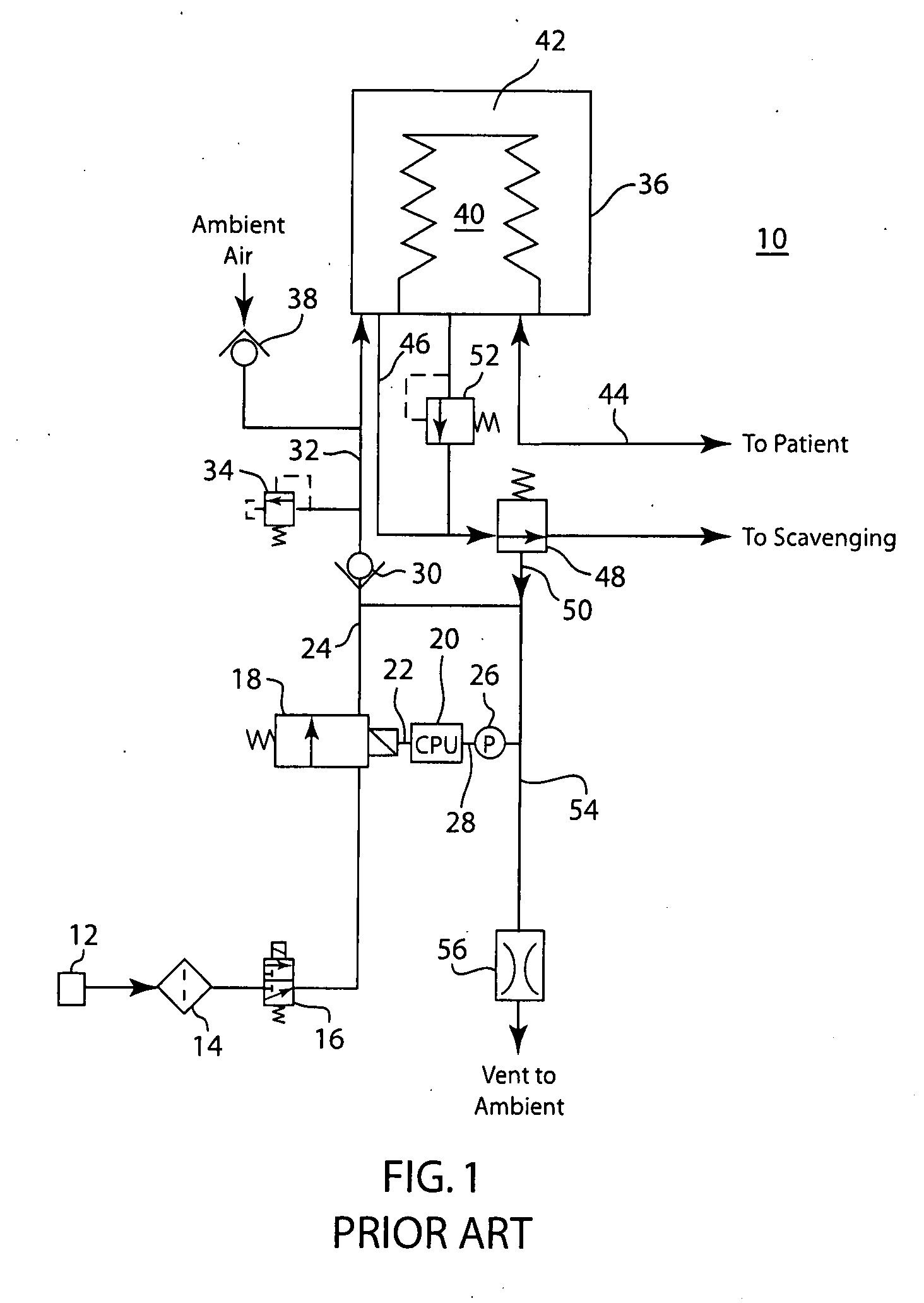
[0020]FIG. 1 depicts a schematic diagram of a ventilatory system 10 known in the art. A ventilator of this system is described in U.S. Pat. No. 5,315,989 to Tobia, which is herein incorporated in its entirety by reference. In ventilatory system 10, a pressurized source of medical gas 12 is connected to a regulator 14 and a gas inlet valve 16. The pressurized medical gas serves as the drive gas for operating the ventilatory system 10. The pressurized gas flows from the inlet valve 16 to an inspiratory flow control valve 18. Typically, the inspiratory flow control valve 18 is a proportional flow solenoid valve, but many other suitable types of valves exist, including single or multiple pulse-width modulated (PWM) two-position valves. The inspiratory flow control valve 18 is controlled by CPU 20 via line 22. The CPU 20 directs the inspiratory flow control valve 18 to open and close according to the pressure that is desired to be in a first inspiratory conduit 24. The pressure in inspir...


PUM


Abstract

A ventilatory system for providing ventilatory support to a patient without the need for an external source of pressurized drive gas. The ventilatory system comprises a drive pump and a controller such that the drive pump collects ambient air and may pressurize it to a pressure determined by the controller. The controller may signal to the drive pump to pressurize the collected ambient air to a first pressure for delivering ventilatory support to a patient and a second pressure for providing PEEP support to a patient. The controller may signal to the drive pump to deliver a targeted flow and / or volume of collected ambient air to the bellows to provide volumetric ventilatory support during inhalation and a PEEP support during exhalation.

Description

FIELD OF THE DISCLOSURE[0001]The disclosure is directed towards mechanical ventilators for providing a patient with respiratory support including the delivery of anesthesia as well as ventilatory support. Specifically, the disclosure is directed towards a mechanical ventilator with increased mobility.BACKGROUND OF THE DISCLOSURE[0002]Patients that have respiratory difficulties often must be placed on a mechanical ventilator. These respiratory difficulties may be pathological in nature or may be due to the fact that the patient is too weak or sedated to independently perform respiration functions. Often, the patient may be spontaneously attempting to breathe but is not able to complete a full respiratory cycle. In these cases, mechanically assisted ventilation is provided. In some mechanically assisted ventilation platforms, a combination of pressure and / or flow sensors detect a patient's breath attempt. Detection of a breath attempt triggers the mechanical delivery of a breath. The ...

Claims


Application Information

Patent Timeline
Patent Type & Authority Applications(United States)
IPC IPC(8): A61M16/08
CPCA61M16/00A61M16/0057A61M16/0075A61M16/0081A61M2016/0039A61M2205/42A61M2016/0027A61M16/0063A61M16/107A61M16/024
Inventor KOLLMEYER, PHILLIP J.KUTKO, STEFAN I.THAM, ROBERTRICK, NORMANWOODS, JONATHAN L.
Owner GENERAL ELECTRIC CO
Why Eureka
Try Eureka