Antenna Diversity System and Slot Antenna Component

a technology of diversity system and antenna component, applied in the direction of antenna support/mounting, radiating element structure, antenna, etc., can solve the problems of absorbing, reflected, scattered and/or diffracted energy carried by the waves, and unable to direct the path (or line-of-sight, los), so as to reduce the overhead pcb area

Active Publication Date: 2008-08-21
FRACTUS
View PDF39 Cites 145 Cited by
  • Summary
  • Abstract
  • Description
  • Claims
  • Application Information

AI Technical Summary

Benefits of technology

[0023]The present invention discloses a new antenna diversity system for wireless devices (such as for instance a mobile phone, a smartphone, a PDA, a MP3 player, a headset, a USB dongle, a laptop, a PCMCIA or Cardbus 32 card) that exhibits good diversity gain, while requiring little PCB area overhead.

Problems solved by technology

As the radiated electromagnetic waves travel from the emitter to the receiver, they encounter obstacles (like for example walls and furniture in indoor environments, or buildings, trees and vehicles in outdoor environments) and as a result some of the energy carried by the waves is absorbed, reflected, scattered and / or diffracted.
The propagation can be furthermore complicated by the fact that in some cases no direct path (or line-of-sight, LOS) will be possible between emitter and receiver.
In typical wireless systems the transmitted signal will encounter several obstacles, giving rise to a multiplicity of propagation paths, and signal components arriving at the receiver with different delays.
This out-of-phase addition can result in a temporary cancellation of the received signal (phenomenon known as fading), with the subsequent loss of information.
This problem becomes more critical for wireless systems involving data transmission, because fading is responsible for the interruption of the communication, the loss of data (and subsequent increase in bit error rate, BER), and the decrease of the data bit rate.
All these aspects degrade the quality of service (QoS) of the system.
Although these techniques can improve substantially the QoS of the system, it is difficult to implement an effective antenna diversity system in a wireless portable device (such as for instance a mobile phone, a smartphone, a PDA, a MP3 player, a headset, a USB dongle, a laptop, a PCMCIA or Cardbus 32 card) due to the reduced dimensions and form factors of current wireless devices, which will become even more critical in future devices as the trend is towards reducing even further their dimensions.
However, the typical dimensions of the printed circuit boards (PCB) of wireless devices makes space diversity difficult to implement in such devices and lead to a poor diversity gain (i.e., improvement in the QoS).
Furthermore, the real estate requirements of several printed antennas or chip antennas (both in terms of antenna footprint and antenna clearance from ground plane) on the same PCB might be prohibitive for a typical wireless device.
The problem will only aggravate as the trend is to put more functionality and services in smaller PCBs.
Although this approach would ease the requirements of PCB area for the antenna, the shapes and form factors of real PCBs make it difficult to obtain nearly orthogonal polarizations.
However, as it happens with polarization diversity, the shapes and form factors of real PCBs lead to antennas with fairly omnidirectional pattern, hence resulting in poor diversity gain.
In addition to it, they have the disadvantage of not being modular, making it necessary to design the antenna to fit in a specific device.

Method used


Image

  • Antenna Diversity System and Slot Antenna Component
  • Antenna Diversity System and Slot Antenna Component
  • Antenna Diversity System and Slot Antenna Component

Examples


embodiment 1

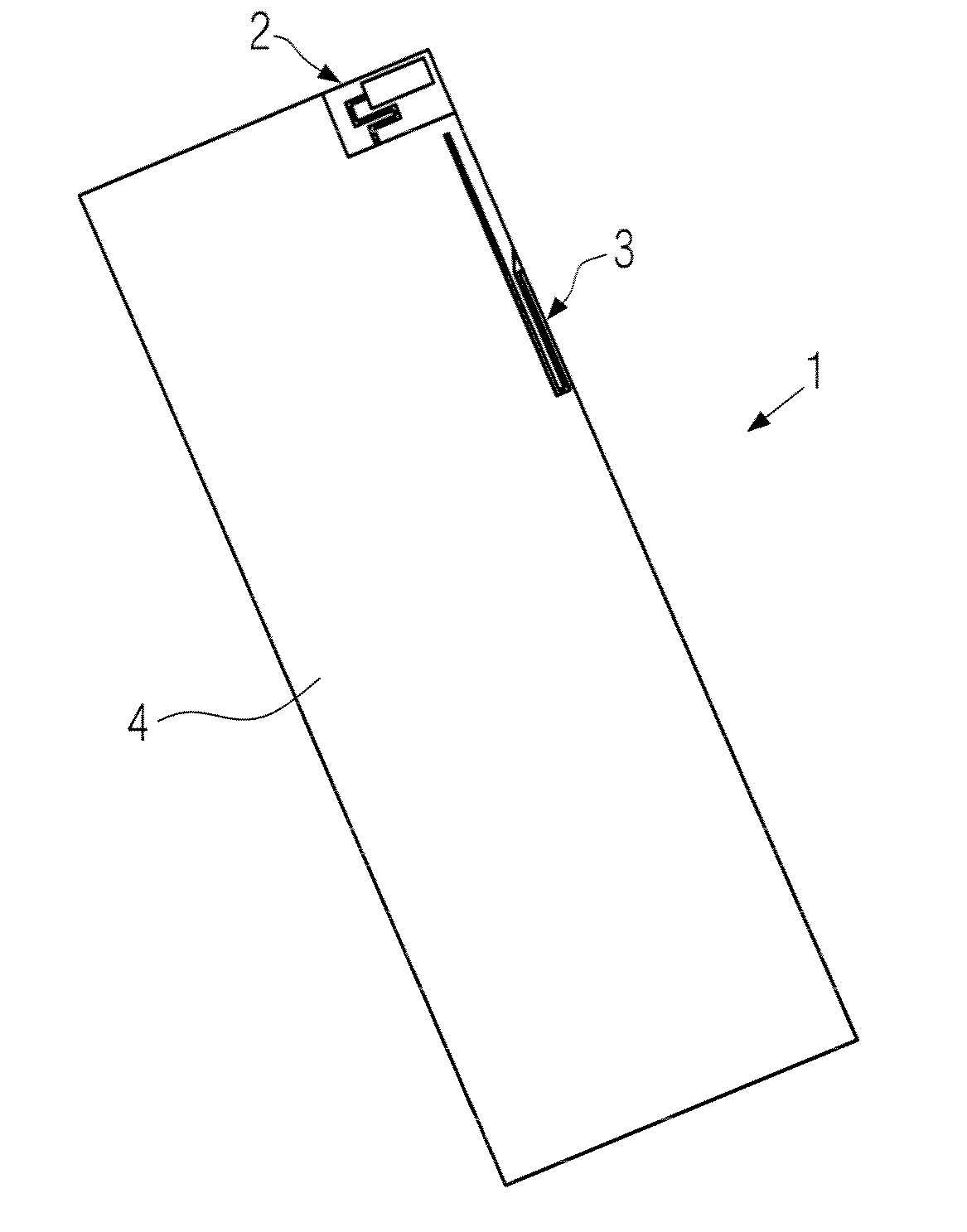
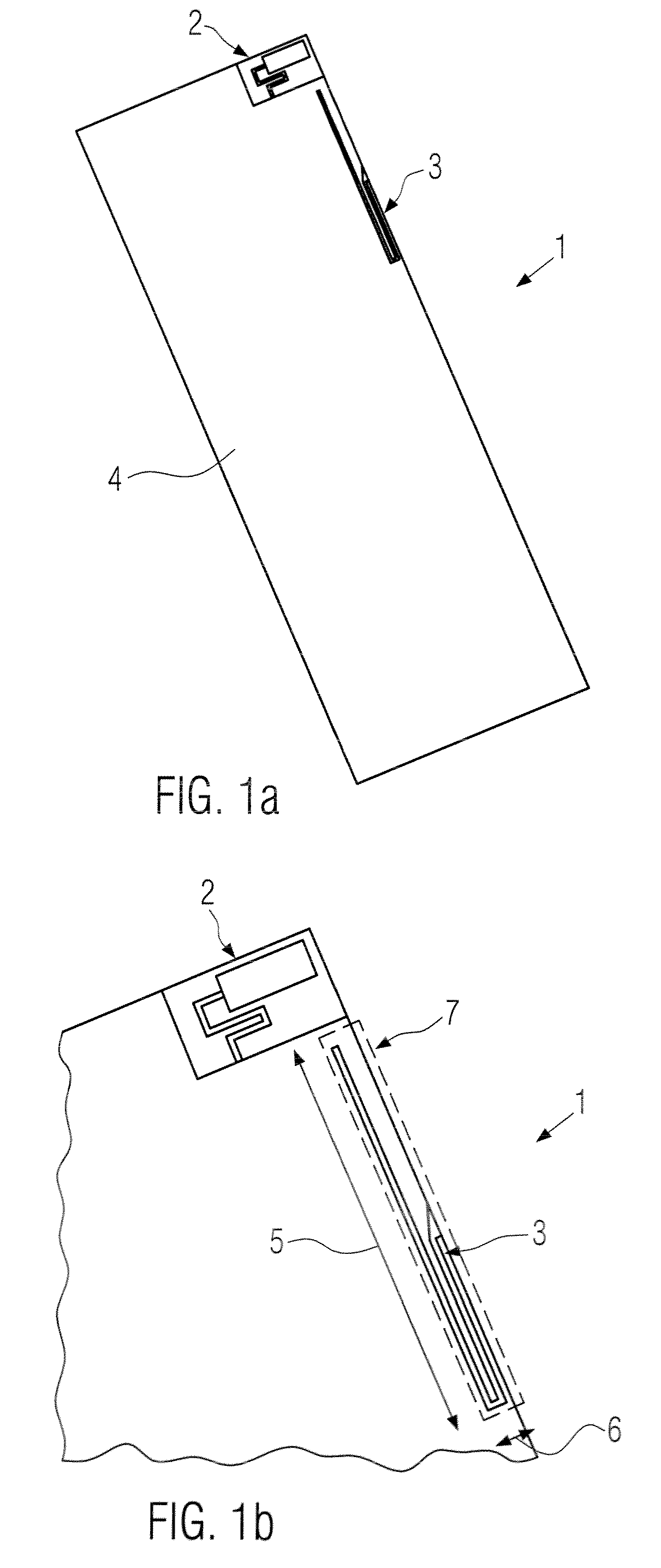
[0168]In this embodiment (for instance, the one shown in FIG. 1), the wireless device with diversity system comprises a slot antenna 3 printed or etched on the ground plane of the PCB 4, and an antenna component (or chip antenna) 2 that can be mounted on the PCB 4 as a SMT component.

embodiment 2

[0169]This other embodiment, represented in FIG. 6, implements a diversity system for a wireless device combining a slot antenna 43 printed on the PCB 41 and a printed monopole antenna or IFA 42.

embodiment 3

[0170]In another example in FIG. 7, the diversity system of the wireless device comprises a first antenna 53 being a printed slot antenna, and a second antenna 52. The second antenna 52 is for operating not only in the same frequency band as the one of the first antenna 53, but also operating, at least, at some other frequency band used for mobile telephone systems. In some cases, the said second antenna 52 will be advantageously a monopole antenna, an IFA, a patch antenna, or a PIFA.


PUM


Abstract

The present invention refers to an antenna diversity system comprising at least a first antenna and a second antenna wherein the first antenna substantially behaves as an electric current source or as a magnetic current source, and the second antenna substantially behaves as an electric current source or as a magnetic current source and a corresponding wireless device. Further the invention relates to an SMT-type slot-antenna component comprising at least one conductive surface or sheet of metal in which the pattern of a slot is created, at least one contact terminal accessible from the exterior of said component to electrically connect the conductive surface included in the slot-antenna component with the ground plane of a circuit board such as a printed circuit board and a corresponding wireless device.

Description

[0001]This application is related to the European patent applications EP 05104026 filed on May 13, 2005 and EP06110437 filed on Feb. 27, 2006 and to the U.S. patent applications U.S. 60 / 680,693 filed on May 13, 2005 and U.S. 60 / 778,323 filed on Mar. 2, 2006. The priority of those four applications is claimed and they are incorporated herein by reference.BACKGROUND OF THE INVENTION[0002]The present invention relates to an antenna diversity system in particular to an antenna diversity system of a wireless device.[0003]In known wireless systems, different mechanisms contribute to the propagation of a radio frequency signal. As the radiated electromagnetic waves travel from the emitter to the receiver, they encounter obstacles (like for example walls and furniture in indoor environments, or buildings, trees and vehicles in outdoor environments) and as a result some of the energy carried by the waves is absorbed, reflected, scattered and / or diffracted. Thus, not only the signal component...

Claims


Application Information

Patent Timeline
Patent Type & Authority Applications(United States)
IPC IPC(8): H01Q21/28H01Q13/10H01Q1/38
CPCH01Q1/242H01Q1/38H01Q21/28H01Q13/10H01Q21/24H01Q9/30
Inventor SOLER CASTANY, JORDIMUMBRU FORN, JOSEPPUENTE BALIARDA, CARLES
Owner FRACTUS
Why Eureka
Try Eureka