Fuel Injection System Suitable for Low-Viscosity Fuels

a fuel injection system and low viscosity technology, applied in the direction of fuel injecting pumps, process and machine control, instruments, etc., can solve the problems of reducing the clearance in the spool, affecting hydraulic efficiency and controllability, and the volume to be passed through the injector and control valve to obtain a given engine power, etc., to achieve the effect of long stem sealing length, small leakage, and relatively large li

Inactive Publication Date: 2008-08-28
VOLVO LASTVAGNAR AB
View PDF10 Cites 17 Cited by
  • Summary
  • Abstract
  • Description
  • Claims
  • Application Information

AI Technical Summary

Benefits of technology

[0006]The poor lubricity and potentially big leakage of the low-viscosity fuels, on one hand, and their low-sooting combustion properties, on the other hand, dictate the choice of relatively low injection pressures. Low fuel pressure levels not only require extra large flow areas in the control valves of the injection system, but also make it necessary to use high-flow nozzles in order to keep the injection time periods short enough for good engine fuel efficiency. The design of conventional high-pressure diesel injection nozzles which are used in the system disclosed in U.S. Pat. No. 6,189,517 B1, limits the size and number of injection orifices that can be used. Another unfavorable aspect of using conventional high-pressure diesel injection nozzles in a low-viscosity injection system is their relatively high cost and complexity.
[0014]Due to the design of the control system of the present invention, characterized by the fact that the electrically operated valves do not directly control the full flow of fuel to be injected into the engine, these valves and their actuators can be made sufficiently small to be fitted directly in the injector. This minimizes the dead hydraulic volumes and helps achieve more accurate control of fuel injection, in particular, of small fuel quantities.

Problems solved by technology

One technical difficulty that arises when a common rail injection system is designed for use with low-viscosity fuels is that, due to relatively low specific energy of low viscosity fuels such as DME, the volume to be passed through the injectors and control valves to obtain a given engine power, is relatively big.
This necessitates relatively large controlled areas in the valves, which usually conflicts with the requirements of small overall dimensions, quick response times and small control and static leakages in the injection system.
Such leakages have been found to negatively affect hydraulic efficiency and controllability even in the conventional diesel fuel injection systems.
Reducing clearances in the spool to limit the leakage is not technically feasible both because they are already close to a minimum and because low-viscosity fuels have poor lubricity, which greatly increases the risk of seizure in close-fit spools.
However, this principle can hardly be realized to control full flow of fuel to be injected, especially in the case of increased volume deliveries necessary when using DME, because the size of the valve becomes prohibitively large for the good response times and acceptable electrical power consumption to be maintained.
The poor lubricity and potentially big leakage of the low-viscosity fuels, on one hand, and their low-sooting combustion properties, on the other hand, dictate the choice of relatively low injection pressures.
The design of conventional high-pressure diesel injection nozzles which are used in the system disclosed in U.S. Pat. No. 6,189,517 B1, limits the size and number of injection orifices that can be used.
Another unfavorable aspect of using conventional high-pressure diesel injection nozzles in a low-viscosity injection system is their relatively high cost and complexity.
Yet another negative aspect of using conventional diesel nozzles in a low-viscosity fuel system is that the leakage past the needle guide of such nozzles can also become relatively large.
The fuel cooler may otherwise be necessary because higher leakage causes conversion of more hydraulic power into heat which has to be removed from the system.
Due to its small size, the pilot valve can be hydraulically unbalanced with positive sealing of both seats, and the leakage past the valve stem is also small due to its small diameter, typically 3 mm, and relatively long stem sealing length.

Method used


Image

  • Fuel Injection System Suitable for Low-Viscosity Fuels
  • Fuel Injection System Suitable for Low-Viscosity Fuels
  • Fuel Injection System Suitable for Low-Viscosity Fuels

Examples


Embodiment Construction

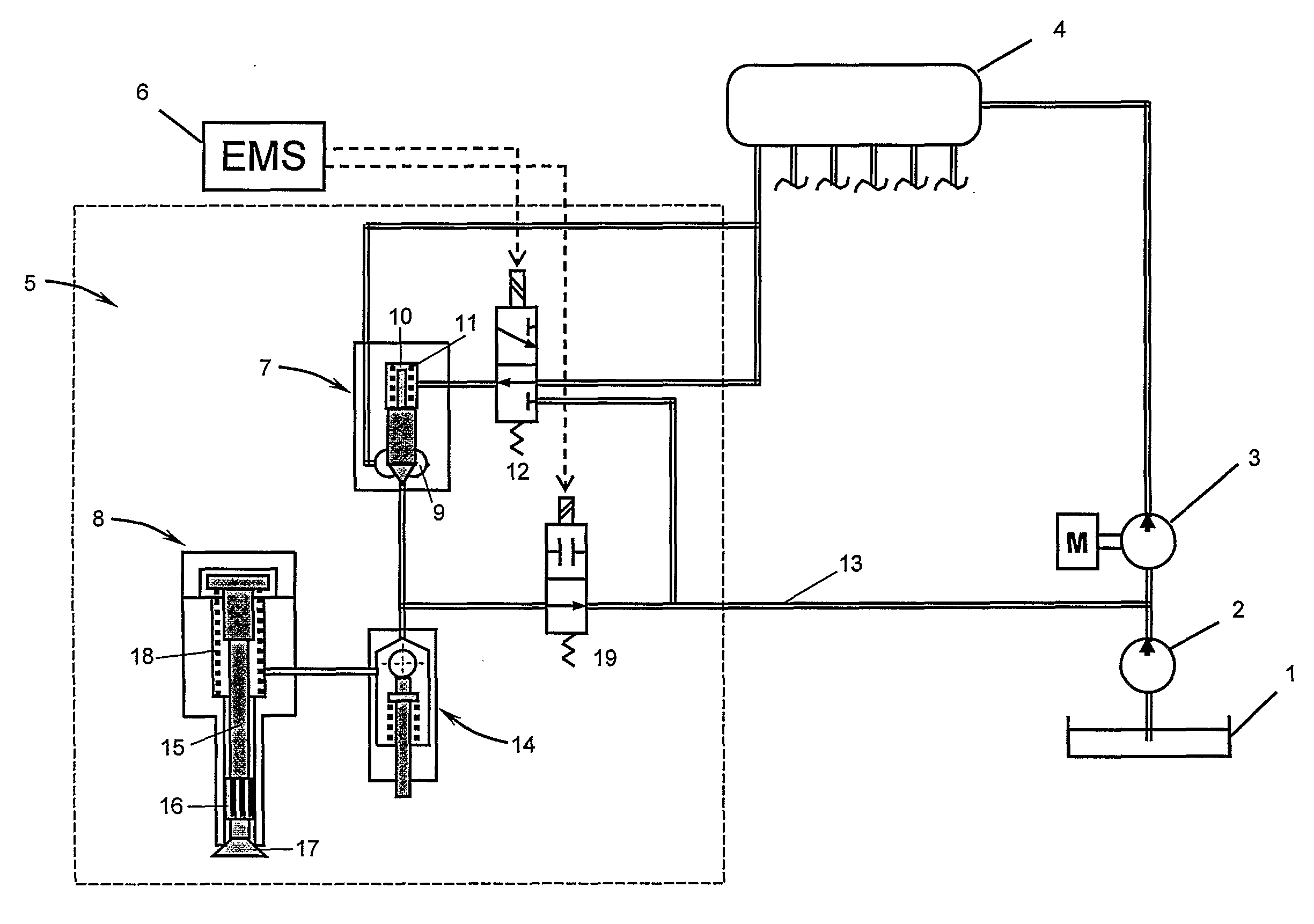
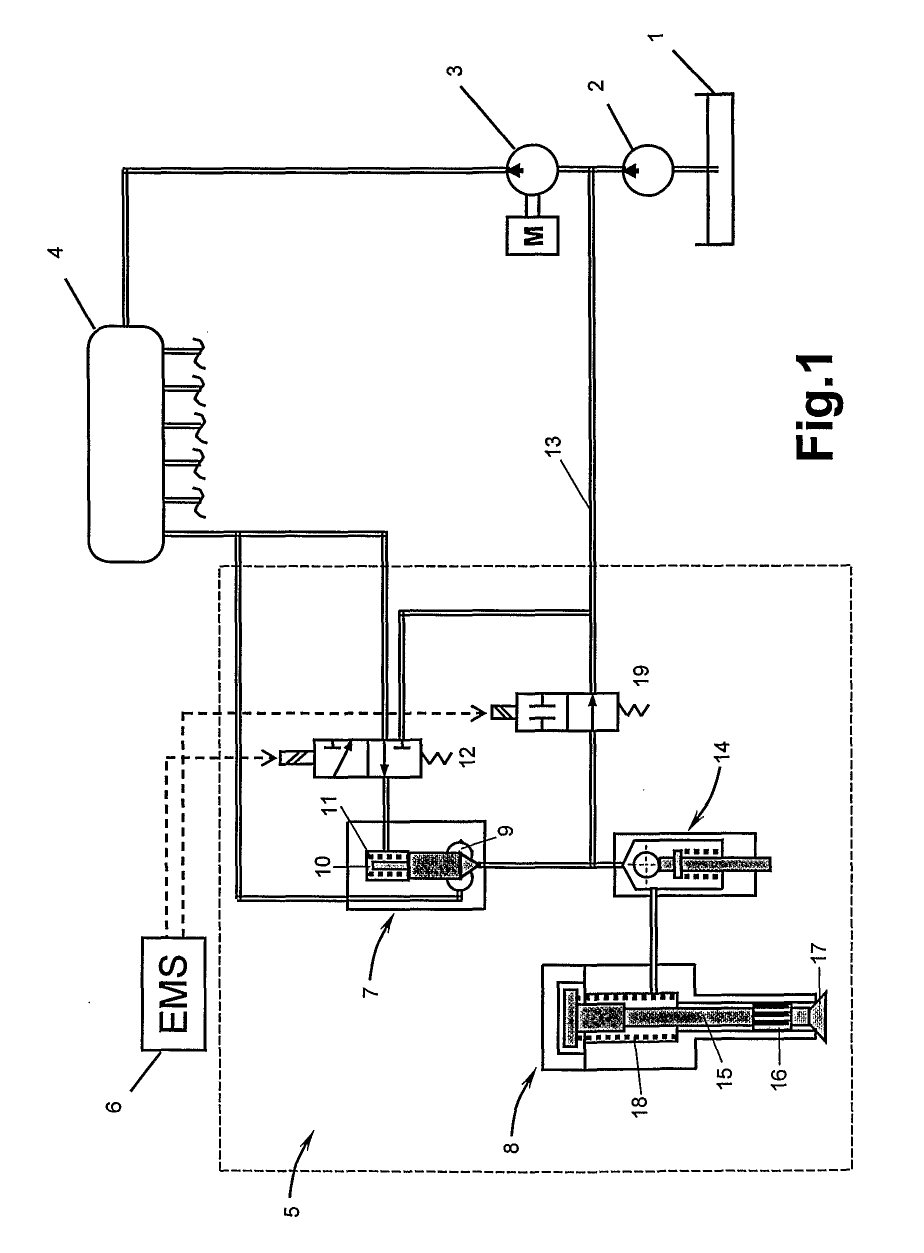
[0021]Referring to FIG. 1, there is provided a low-viscosity fuel feed system including a fuel tank 1, a feed pump 2 and associated components (not shown), a high-pressure pump 3, a common rail 4, to which a plurality of injectors 5 are connected, and an engine management system 6. A hydraulically operated valve 7 is connected between the common rail 4 and the inlet of a nozzle 8, the inlet of the hydraulically operated valve 7 being connected to the common rail 4. The hydraulically operated valve preferably has a precision-matched stem and forms an outlet chamber 9 and a control chamber 10, and is preferably biased towards its closed position by a resilient means 11. The control chamber 10 of the valve 7 can be connected by a three-way pilot valve 12 to either the common rail 4 or a return line 13, depending on commands from the Engine Management System (EMS) 6. The outlet of the hydraulically operated valve 7 is connected to the inlet of the nozzle 8 via a differential hydraulic v...


PUM


Abstract

A fuel injection system for an internal combustion system includes an Engine Management System (EMS), a fuel feed pump, a return line, a high-pressure pump, supplying fuel under pressure to a common rail, a hydraulically operated valve forming an outlet chamber connected to the common rail and a control chamber, the valve being designed such that, in its closed position, the valve prevents the flow out of the outlet chamber, and an electrically operated pilot valve. A nozzle with a resilient member that biases the nozzle towards closing is connected to the outlet of the hydraulically operated valve in such a way that pressure at the outlet of the hydraulically operated valve tends to overcome the force of the resilient member and open the nozzle. An electrically operated spill valve is connected between the outlet of the hydraulically operated valve and the return line.

Description

BACKGROUND AND SUMMARY[0001]The present invention relates to fuel injection systems for internal combustion engines, in particular, systems suitable for injection of low viscosity fuels such as Di-Methyl Ether (DME) into compression-ignition engines.[0002]Some low-viscosity fuel injection systems have been designed following the principle of the known high-pressure common rail systems for diesel fuel, in which fuel is pressurized by a single pump into a pressure vessel or rail that is common for a plurality of injectors, and injections are controlled by electrically actuated valves placed between the common rail and the injectors. This kind of injection system is better suited for fuels with widely variable, pressure and temperature-dependent properties typical to these of DME, than injection systems based on the pump-line-nozzle or unit injector principle, partially because the processes of creating and controlling the injection energy for each injection are divided in time and the...

Claims


Application Information

Patent Timeline
Patent Type & Authority Applications(United States)
IPC IPC(8): F02M69/54F02M69/46F02D7/00
CPCF02M45/00F02M55/002F02M61/08F02M61/205F02M2200/70F02M63/0029F02M63/0043F02M63/0045F02M63/0047F02M63/0005F02M21/0239F02M21/0245Y02T10/30
Inventor YUDANOV, SERGI
Owner VOLVO LASTVAGNAR AB
Why Eureka
Try Eureka