Single, Right-Angled End-Block

a right-angled, single technology, applied in the field of endblocks, can solve the problems of extensive modification of existing equipment, and achieve the effect of easy draining of coolan

Inactive Publication Date: 2008-08-28
SOLERAS ADVANCED COATINGS NV
View PDF27 Cites 19 Cited by
  • Summary
  • Abstract
  • Description
  • Claims
  • Application Information

AI Technical Summary

Benefits of technology

[0019]It is an object of the invention to provide an end-block that on its own can carry a rotatable tubular magnetron parallel to the wall on which the end-block is mounted. It is an object of the invention to provide a single end, right-angled end-block particularly suited to be mounted on a door or wall of a sputtering apparatus. It is also an object of the invention to provide an end-block with a minimum of axial length. The inventive end-block also provides for easy draining of the coolant in case the target has to be replaced.

Problems solved by technology

One of the drawbacks in using these tubular targets in such display coaters is the need for extensive modification of the currently existing equipment.

Method used


Image

  • Single, Right-Angled End-Block
  • Single, Right-Angled End-Block
  • Single, Right-Angled End-Block

Examples


Embodiment Construction

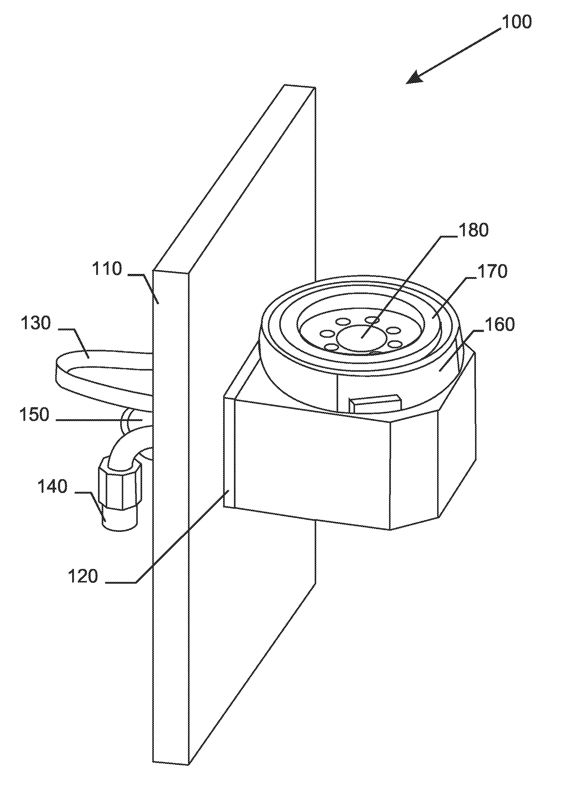
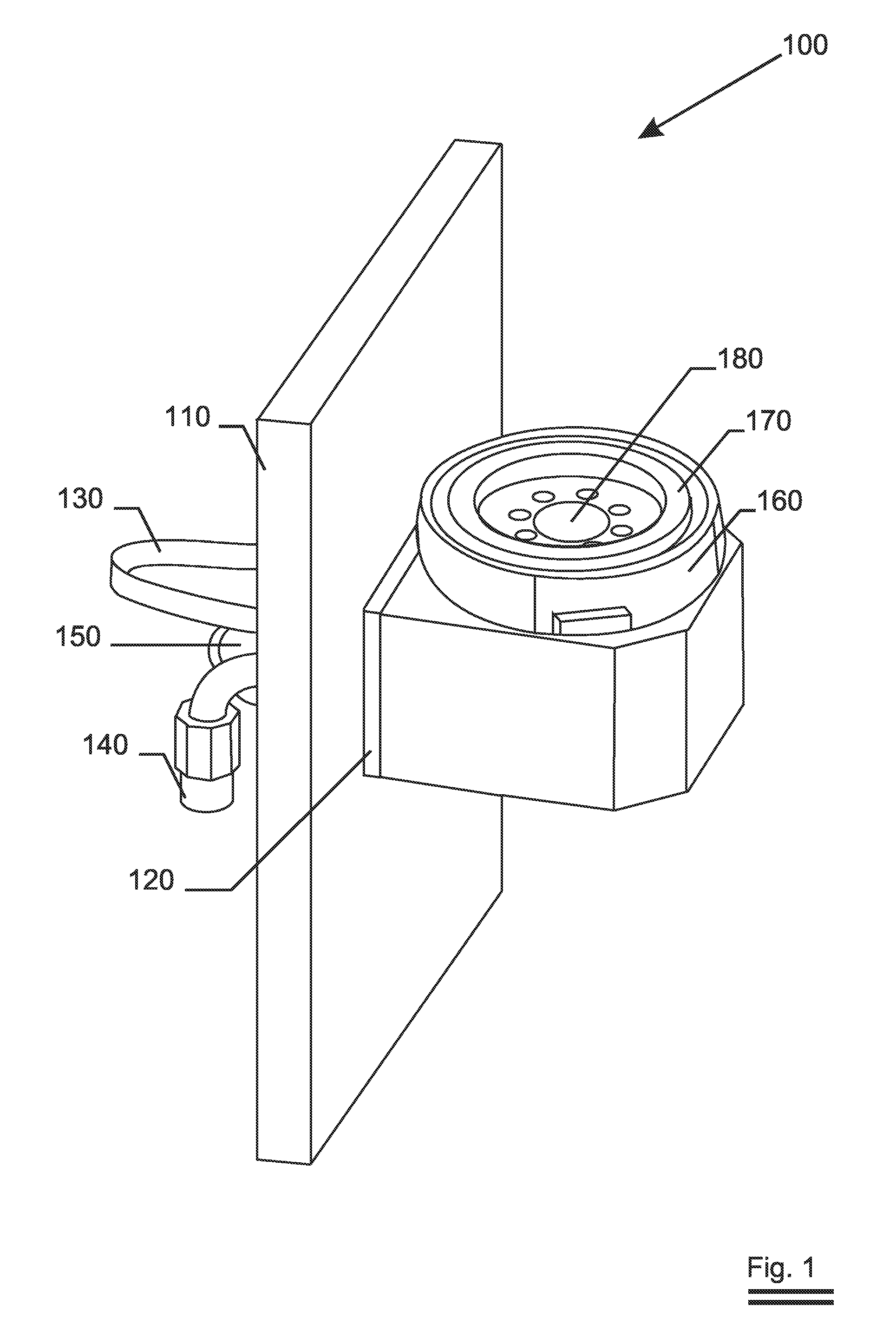
[0038]FIG. 1 is a perspective view of how the inventive end-block is mounted to the wall or the door of a sputtering apparatus. The end-block 100 is mounted to the wall 110 of the sputtering apparatus at the end-block flange 120. From the outside of the apparatus a drive means—in this case a synchronous belt 130—makes the mounting flange 170 rotate. The target (not shown) rests on this flange and is removably attached to it by means of an interface ring 160. Coolant supply 140 and extraction 150 at the outside connect to flange bore 180. Inside this bore the coolant supply and return are separated from one another (not visible). The magnet bar (not shown) is also inserted and held in this bore.

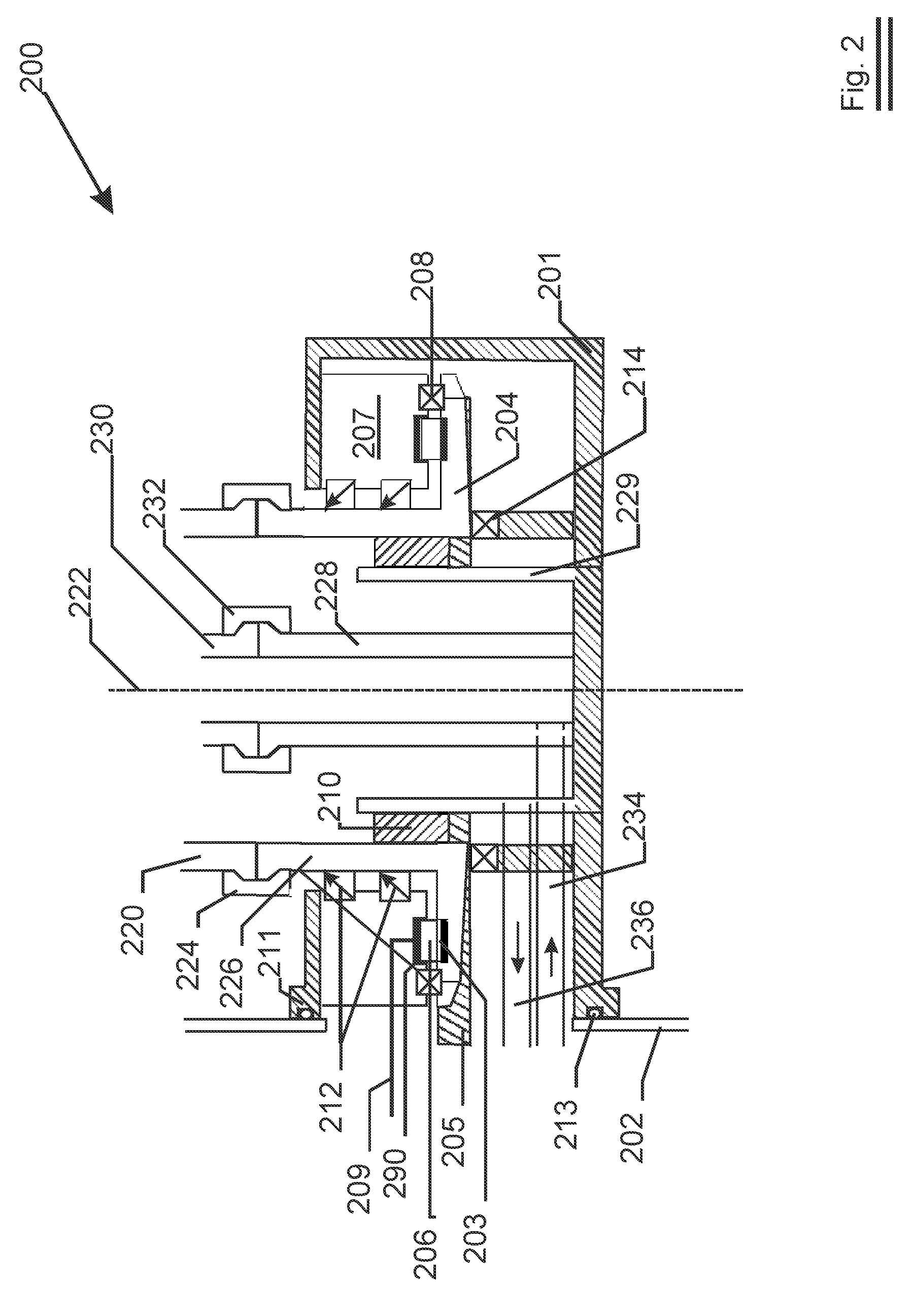
[0039]FIG. 2 shows as schematic cross section of a preferred embodiment. The end-block 200 incorporates a drive means, a rotary electrical contact means, a bearing means, coolant sealing means and vacuum sealing means in a single housing 201. The end-block is mounted to the wall or door 202 of...


PUM

PropertyMeasurementUnit
massaaaaaaaaaa
pressureaaaaaaaaaa
pressureaaaaaaaaaa

Abstract

A single, right-angled end-block is claimed for rotatably carrying a target in a sputtering apparatus. The end-block comprises all necessary means to drive, energise, bear and seal (coolant and gas) the target in the sputtering apparatus from the outside through a single opening in a wall or door. The right-angled end-block rotates the target around an axis of rotation that is parallel to the wall on which the target is mounted. By preference the end-block is situated below the target in order to allow easy drainage of the coolant.

Description

FIELD OF THE INVENTION[0001]The invention relates to an end-block that is used to rotatably carry a sputtering target in a sputtering apparatus. More in particular it relates to an end-block that integrates all supply functions in one, while the target is mounted substantially parallel to the end-block flange by which it is mounted to the wall of the sputtering apparatus.BACKGROUND OF THE INVENTION[0002]‘Sputter deposition’ or ‘sputtering’ is a coating process in which atoms are dislodged from a target by impingement with kinetic ions and subsequent ejection of those atoms to a substrate. The ions are generated in a free electron plasma ignited in a low pressure sputter gas (usually a noble gas species with a high atomic mass such as argon) by a voltage difference between the cathodic target and an anode. The voltage difference also accelerates the ions to a high kinetic energy towards the target. Only a minor part of the ions' kinetic energy is used to bounce target atoms out of pl...

Claims


Application Information

Patent Timeline
Patent Type & Authority Applications(United States)
IPC IPC(8): C23C14/00
CPCC23C14/3407H01J37/3497H01J37/3405C23C14/35C23C14/54H01J37/3435
Inventor DELLAERT, KRISTDE BOSSCHER, WILMERTDE BOEVER, JOANNESLAPPEIRE, GREGORY
Owner SOLERAS ADVANCED COATINGS NV
Why Eureka
Try Eureka