
Eolic converter

a converter and eosine technology, applied in the direction of propulsive elements, motors, propulsive components, etc., can solve the problem of low loss of flagging, achieve the effect of improving the precision range of medium rotation, increasing or reducing the angular speed, and reducing the loss

Inactive Publication Date: 2008-08-28
DULCETTI FILHO FLAVIO FRANCISCO
View PDF7 Cites 26 Cited by
  • Summary
  • Abstract
  • Description
  • Claims
  • Application Information

AI Technical Summary

Benefits of technology

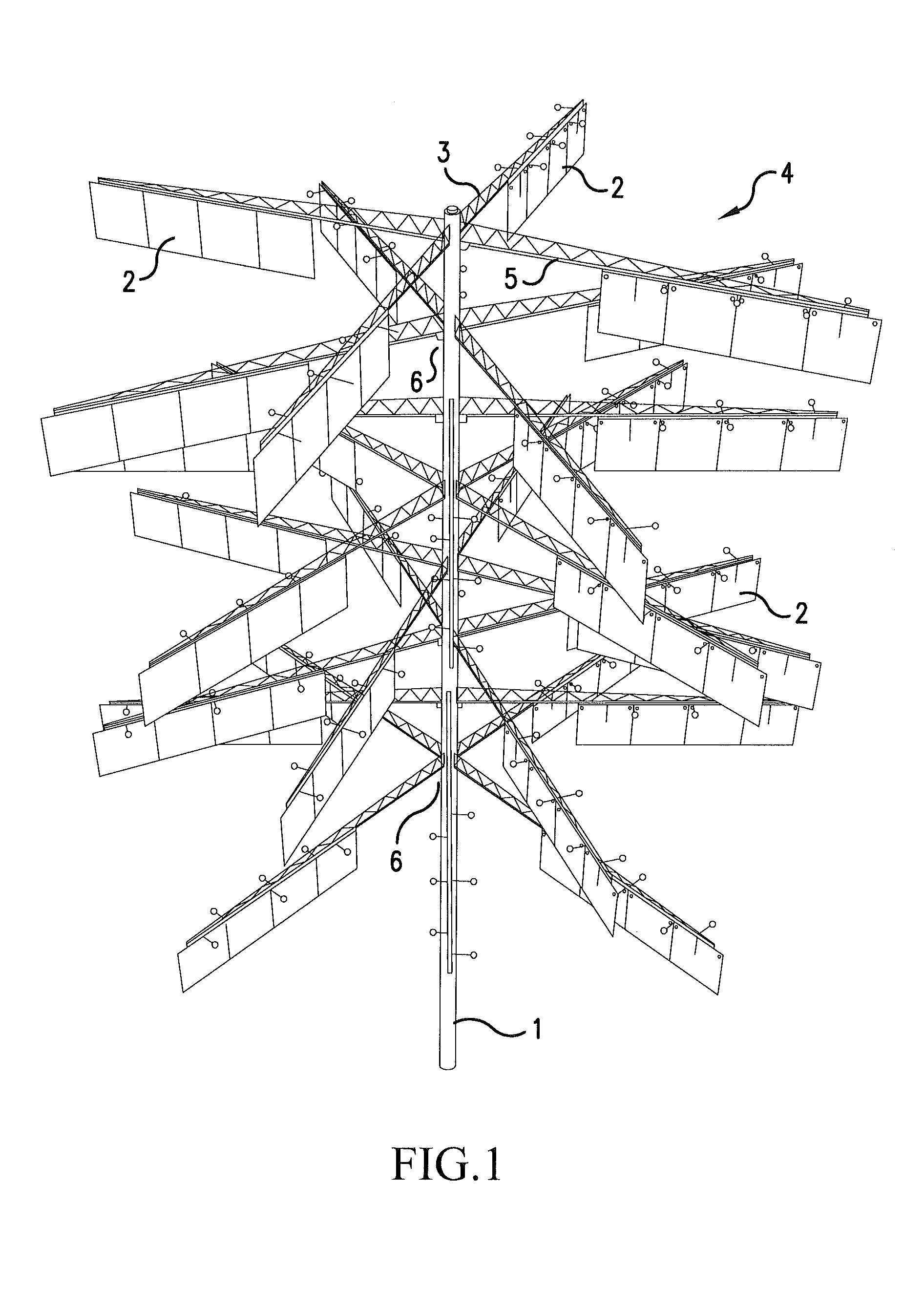
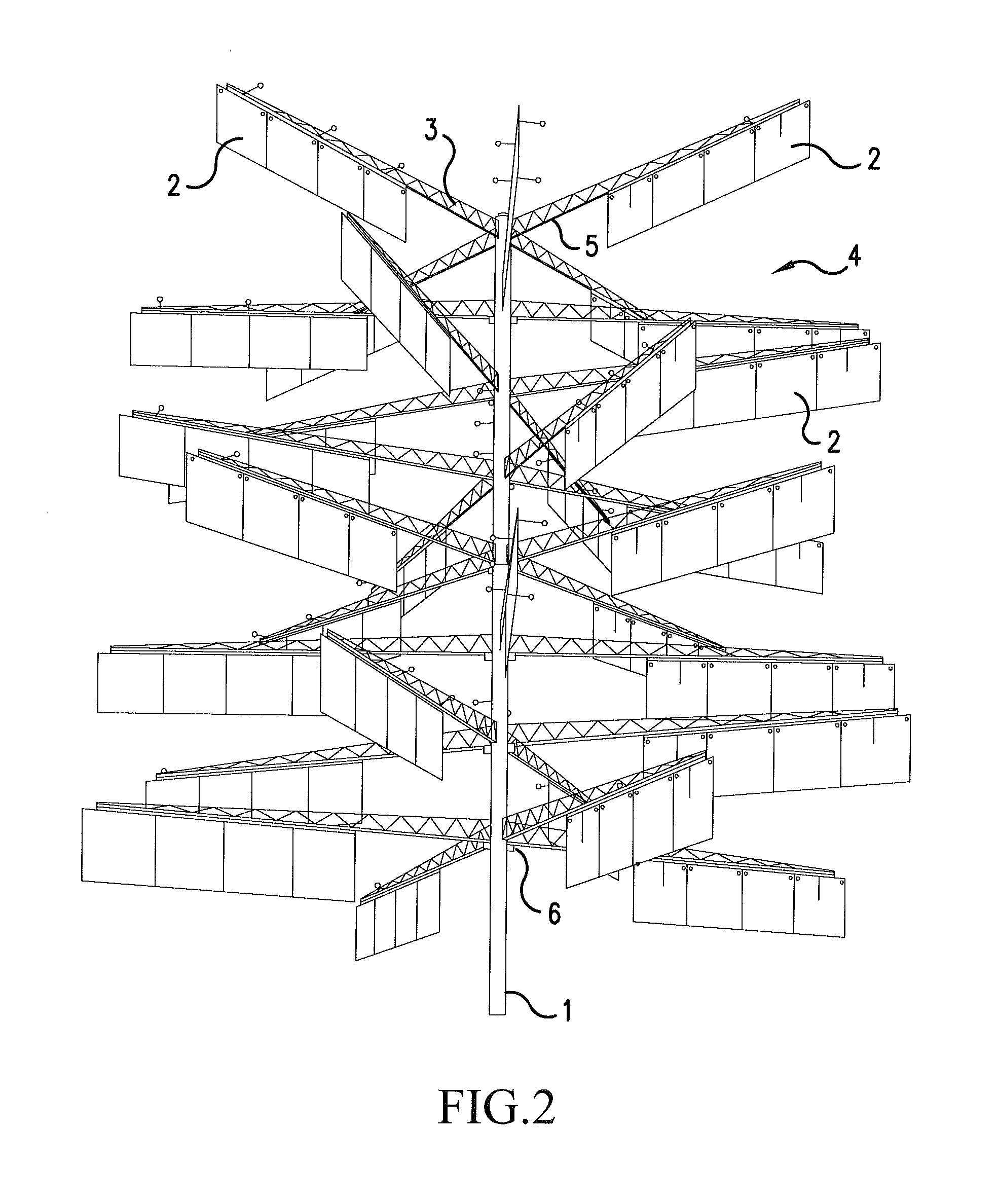
[0029]Based on the state of the art problems mentioned above, a new eolic converter was invented with unpublished characteristics to impel a system of electric power generation by the wind force, in the little, middle and wide scales versions. This system for its conception allows to expand in a gigantic way the area of winds force capture in a same tower, for possessing a structural resignation that will allow the enlargement almost that limitless of the wind force capture aerodynamic panels, with low construction (investment) cost if compared with the current standards used for generation of eolic energy; what will provide the obtaining of an energy with low production cost turning it competitive and still with smaller cost than in the conventional ways today used as hydroelectric, thermoelectrical, nuclear etc, being inverted like this the unfavorable situation in relation to the cost for the viability of the use of eolic energy that needs to be subsidized in a lot of regions or to obtain protected market. The system of the present invention possesses one index among 90 to 98% of the wind force for the transformation in energy rotational mechanical energy, varying this percentile with the wind speed, at the same time in that they are added to this high efficiency, which is much more relevant, the possibility to amplify in several levels of plates without limit for the size of the referred plates, what provides for an only propeller shaft the use of gigantic areas of reception of the winds force for rotate the same shaft, what will allow the use of this system with low values of winds speed. It is foreseen for embodiments of larger load control to provide an controlled and regulated potency output, as the usual in wide scale, free from variations, oscillations and noises, and, alternatively, in places whose the wind is insufficient in some periods, the project foresees a joining to the eolic system generator to a combustion motor with controlled injection, or in places that it already has offer of energy an electric engine will be bound instead of the combustion engine and this electric engine will always be rotating in the same axis of the energy generator, in way to avoid the energy consumption with the boot of this engine, and when the system no more to compensate the start of the failure of the rotation produced by the wind the electric engine will assume the propulsion of the generator in an imperceptible way for the consumer without any cut or oscillation in the energy, providing a hybrid system.
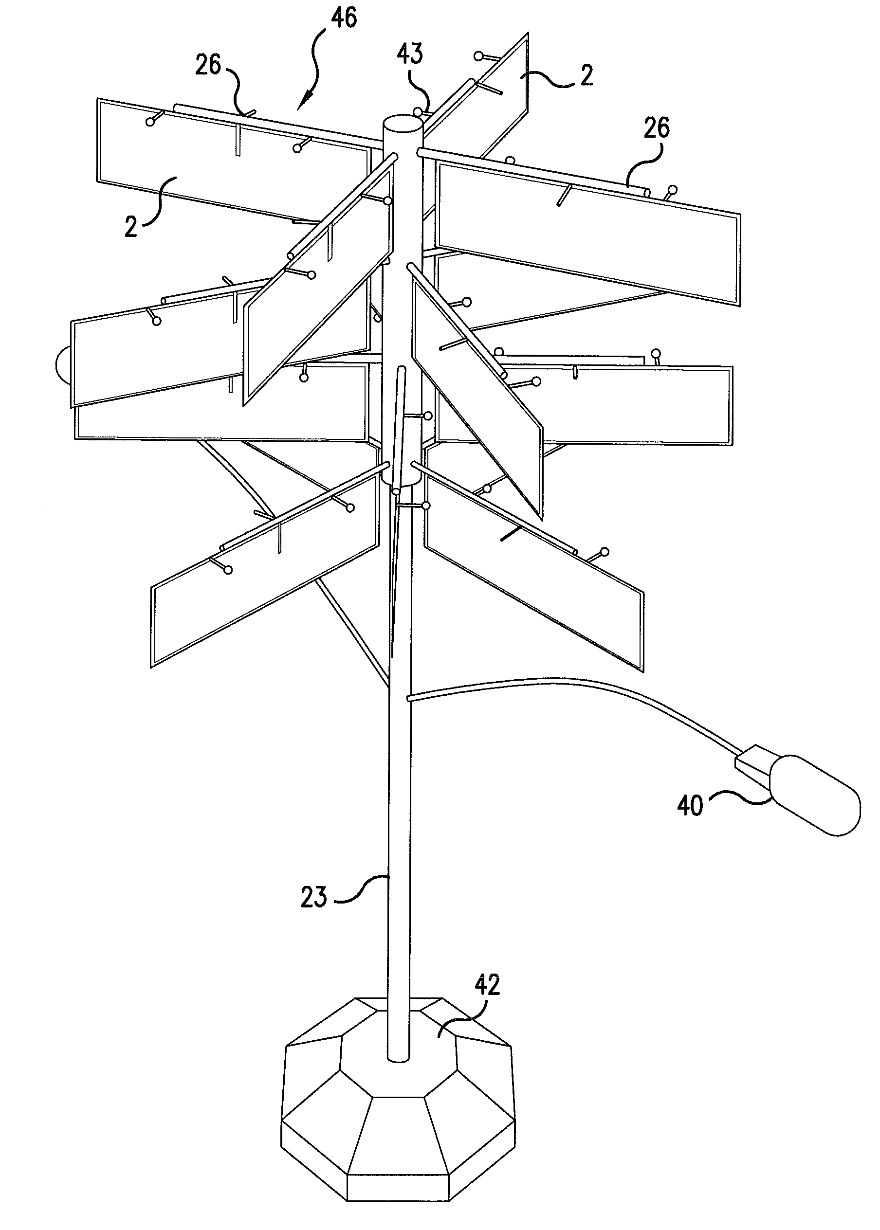
[0031]The technique used in the reception of the eolic force it provides the rotation of a vertical axis, by the wind force when the wind beats in plane aerodynamic plates, which rotate in the horizontal sense describing circles. The aerodynamic surfaces don't use format of shells or helixes, and they are constituted by plates with plane surface with square or rectangular format, with despicable thickness and that are made with extremely light and resistant material against the wind pressures, or then made of heavier materials, being used in this case counterbalances in the panels so that the relative weight for the flagging continue small resulting in low losses for the flagging.

Problems solved by technology

The aerodynamic surfaces don't use format of shells or helixes, and they are constituted by plates with plane surface with square or rectangular format, with despicable thickness and that are made with extremely light and resistant material against the wind pressures, or then made of heavier materials, being used in this case counterbalances in the panels so that the relative weight for the flagging continue small resulting in low losses for the flagging.

Method used


Image

  • Eolic converter
  • Eolic converter
  • Eolic converter

Examples


first embodiment

of the Invention

[0064]This first embodiment of the present invention is destined to the generation of energy in small and big scale, being your structure capable to reach great dimensions. Such configuration is characterized by have a winds pickup system that allows an use above 97% of the wind force for the transformation in rotational mechanical energy, at the same time in that are added to this great output the possibility to add several levels of plates without limit for the size of the referred plates, what provides for an propeller shaft the use of gigantic areas of reception of the winds force where are added the buoyancy produced by the several levels of plates in order to allow a great area of wind reception for rotate a shaft, even with low winds speeds. This system doesn't need to be put in the wind direction because it traction independently of the wind direction always rotating in the sense in that it was programmed to rotate, and it still have a device capable to contr...


PUM


Abstract

The present invention relates to an eolic converter endowed with a winds keeping system that allows an utilization of above 97% of the wind force to transform in mechanical rotational energy, at the same time that is added to this high efficiency the possibility to add several levels of plates without limit of size of the referred plates, what provides for an unique propeller shaft the use of gigantic areas of reception of the wind force where these shafts can be added in order to allow a great area of wind reception to rotate a shaft, even with low values of wind speed, this system doesn't need to be oriented for the wind direction, because traction independently of the moment wind direction, always rotating in the same direction that it was programmed to rotate.

Description

RELATED APPLICATION INFORMATION[0001]This application is a Continuation-In-Part of International Application PCT / BR2006 / 000260, filed Dec. 5, 2007 and claims priority to said International Application under 35 USC §120. The present application also claims priority through said International Application under 35 USC §119 (a-d) of Brazilian Application No. PI0505380-3 filed Dec. 5, 2005 and PI0605878-7 filed Nov. 28, 2006. The contents of each of the above applications is incorporated in their entirety by reference.FIELD OF INVENTION[0002]The present invention is applied to the electric power generation through the transformation of the eolical energy in a mechanical energy in a controlled way, working equipments for the electric power generation or hydraulic bombs, as well as rotors in general, with regulated potency exit supplying a stable independently of the wind speed.STATE OF THE ART[0003]The traditional eolical converters are characterized by possess helixes that rotate in the ...

Claims


Application Information

Patent Timeline
IPC IPC(8): F03D9/00F03D7/00
CPCF03D3/02F03D3/064F03D3/067F03D9/00Y02E10/74F05B2240/911F05B2240/9113F05B2270/1014Y02E10/728F05B2240/40
Inventor DULCETTI FILHO, FLAVIO FRANCISCO
Owner DULCETTI FILHO FLAVIO FRANCISCO
Learn More