Methods and apparatus for programmable active inductance
- Summary
- Abstract
- Description
- Claims
- Application Information
AI Technical Summary
Benefits of technology
Problems solved by technology
Method used
Image
Examples
Embodiment Construction
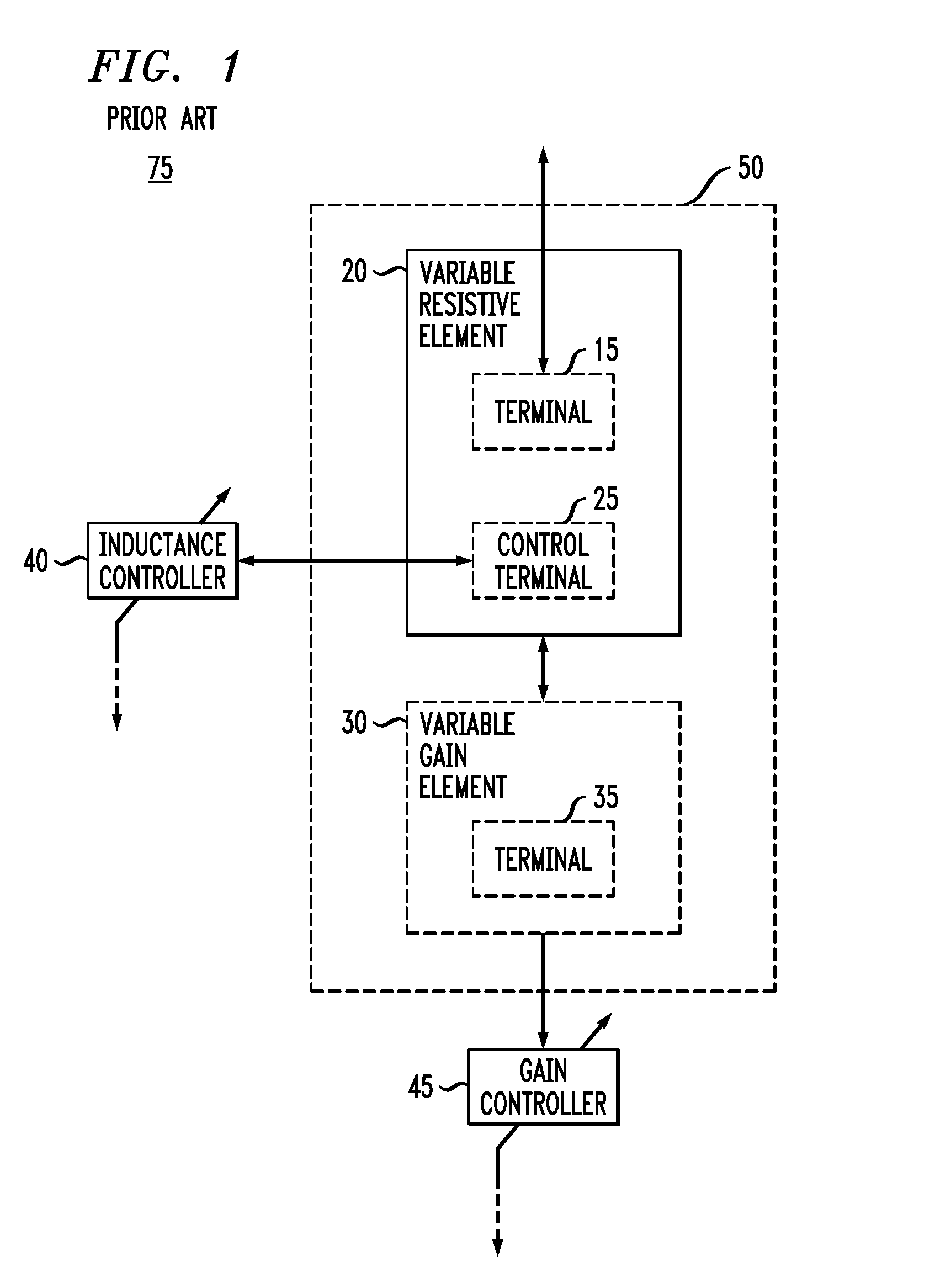
[0023]FIG. 1 is a block diagram illustrating a conventional apparatus 50 and system 75 in accordance with the teachings of U.S. patent application Ser. No. 10 / 929,843, entitled “Three-Terminal, Tunable Active Inductor,” incorporated by reference herein. As shown in FIG. 1, the first apparatus 50 comprises a variable resistive element 20 and a variable gain element 30. The first system 75 comprises the variable resistive element 20 and the variable gain element 30, in conjunction with an inductance controller 40 and a gain controller 45.
[0024]The variable resistive element 20 has a control terminal 25, as a first terminal of the apparatus 50, that provides for coupling to the inductance controller 40. The inductance controller 40 controls the resistance of the variable resistive element 20, and may receive and be responsive to feedback from other portions of any circuit coupled to the system 75. As shown in FIG. 1, the variable resistive element 20 also includes a terminal 15, as a s...
PUM
 Abstract
Description
Claims
Application Information
 - R&D
- Intellectual Property
- Life Sciences
- Materials
- Tech Scout
- Unparalleled Data Quality
- Higher Quality Content
- 60% Fewer Hallucinations
Browse by: Latest US Patents, China's latest patents, Technical Efficacy Thesaurus, Application Domain, Technology Topic, Popular Technical Reports.
© 2025 PatSnap. All rights reserved.Legal|Privacy policy|Modern Slavery Act Transparency Statement|Sitemap|About US| Contact US: help@patsnap.com


