
Catalyst coated membranes and sprayable inks and processes for forming same

a catalyst and coating technology, applied in the field of fuel cell manufacturing, can solve the problems of difficult to employ known methods in high-volume manufacturing operations, loss of valuable catalysts, and need for relatively thick coatings

Inactive Publication Date: 2008-08-28
CABOT CORP
View PDF13 Cites 119 Cited by
  • Summary
  • Abstract
  • Description
  • Claims
  • Application Information

AI Technical Summary

Benefits of technology

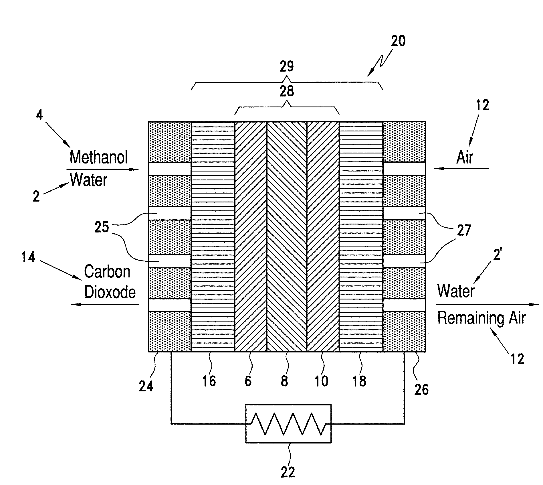
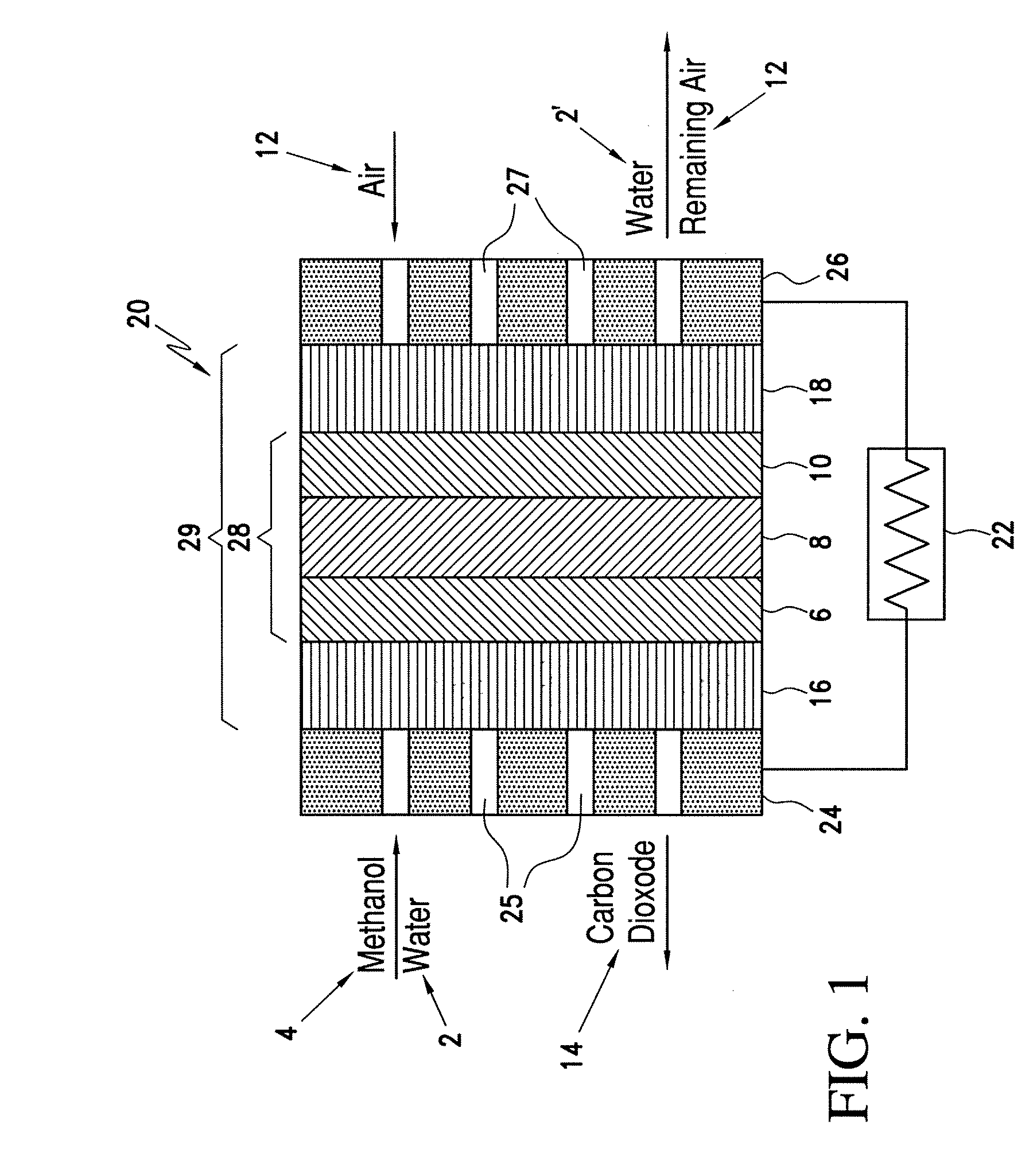
[0011]The present invention is directed to inks and processes for forming catalyst coat

Problems solved by technology

However, the known methods are difficult to employ in high volume manufacturing operations.
Known coating techniques such as painting, patch coating and screen printing are typically slow, can cause loss of valuable catalyst and require the application of relatively thick coatings.
In addition, known techniques for spraying experience various problems, including, but not limited to, sagging, slumping, drooping, swelling, and other problems associated with excess “wetness” of the membrane.
Swelling in particular causes serious problems, and a number of patents have been granted that address this issue.

Method used


Image

  • Catalyst coated membranes and sprayable inks and processes for forming same
  • Catalyst coated membranes and sprayable inks and processes for forming same
  • Catalyst coated membranes and sprayable inks and processes for forming same

Examples


example 1

Preparation of Cathode Ink using Platinum, Nominally 60% on Carbon Black of Johnson Matthey Product Number 44171

[0235]Cathode ink was prepared as follows. 6 grams of deionized water was added to 1 gm of 60-wt % platinum on carbon. 3.53 grams of 5 wt. % NAFION® perfluorinated ion exchange resin solution (vehicle: lower aliphatic alcohol / water (20%) solution (EW1100) containing 2-propanol, 1-propanol and methanol) was then added to the mixture. The resulting mixture was horn sonicated in an ice bath for 10 minutes (750W, using 20% of maximum power). The ink stability was monitored using MICROTRAC® particle size distribution measurement. The ink viscosity was monitored using the VISCOMETER®. The PSD and viscosity as a function of time are tabulated in Table 2.

example 2

Preparation of Cathode Ink using Platinum, Nominally 60% on Carbon Black of Cabot Corporation Product Number PPC965465F

[0236]A cathode ink was prepared as follows. 6 grams of deionized water was added to 1 gm of 60-wt% platinum on carbon. 3.53 grams of 5 wt. % NAFION® perfluorinated ion exchange resin solution (vehicle: lower aliphatic alcohol / water (20% ) solution (EW1100) containing 2-propanol, 1-propanol and methanol) was then added to the mixture. The resulting mixture was horn sonicated in an ice bath for 10 minutes (750W, using 20% of maximum power). The ink stability was monitored using MICROTRAC® particle size distribution measurement. The ink viscosity was monitored using the VISCOMETER®. The PSD and viscosity as a function of time are tabulated in Table 2.

example 3

Preparation of Anode Ink using Platinum, Nominally 40% and Ruthenium Nominally 20% on Carbon Black of Cabot Corporation Product Number HPR375079A

[0237]Anode ink was prepared as follows. 8 grams of deionized water was added to 1-gram platinum / ruthenium black catalyst particles. The mixture was horn sonicated in ice at duty cycle 50 amplitude 20% for 10 minutes (750W, using 20% of maximum power). 3.53 grams of 5 wt. % NAFION® perfluorinated ion exchange resin solution (vehicle: lower aliphatic alcohol / water (20% ) solution (EW 1100) containing 2-propanol, 1-propanol and methanol) was then added to the mixture. The final mixture was again horn sonicated in ice, duty cycle 50 amplitude 20% for 5 minutes (750W, using 20% of maximum power). The ink stability was monitored using MICROTRAC® particle size distribution measurement. The ink viscosity was monitored using the VISCOMETER®. The PSD and viscosity as a function of time are tabulated in Table 2.


PUM

PropertyMeasurementUnit
Timeaaaaaaaaaa
Percent by massaaaaaaaaaa

Abstract

The invention is directed to highly porous catalyst coated membranes and to sprayable inks and processes for forming catalyst coated membranes. In one aspect, the invention is to a sprayable ink, comprising catalyst particles, polymer electolyte ionomer, and a vehicle for dispersing the catalyst particles and polymer electolyte ionomer. In another aspect, the process comprises the steps of depositing an ink comprising catalyst particles and a vehicle onto a membrane and vaporizing from 40 to 95 weight percent of the vehicle from the sprayed ink under conditions effective to form a catalyst layer on the membrane. Preferably, the depositing and vaporizing steps are alternated to form multiple stacked catalyst layers on the membrane.

Description

BACKGROUND OF THE INVENTION[0001]1. Field of the Invention[0002]The invention relates to manufacturing of fuel cells. More particularly, the invention relates to catalyst coated membranes for use in fuel cells and to inks and processes for forming catalyst coated membranes.[0003]2. Background Art[0004]Fuel cells are electrochemical cells that convert reactants, namely fuel and oxidant fluid streams, to generate electric power and reaction products. A broad range of reactants can be used in fuel cells and such reactants may be delivered in gaseous or liquid streams. For example, the fuel stream may be substantially pure hydrogen gas, a gaseous hydrogen-containing reformate stream, or an aqueous alcohol, for example methanol in a direct methanol fuel cell (DMFC). The oxidant may, for example, be substantially pure oxygen or a dilute oxygen stream such as air.[0005]DMFC's are particularly desirable for small electronic equipment applications. Non-limiting examples of such equipment inc...

Claims


Application Information

Patent Timeline
IPC IPC(8): H01M8/10B05D1/02B05D3/00C08K5/05C09D11/00
CPCC09D11/30Y02E60/522H01M4/861H01M4/8642H01M4/8652H01M4/8657H01M4/881H01M4/886H01M4/8882H01M4/90H01M4/92H01M4/921H01M4/925H01M4/926H01M4/928H01M8/1011H01M8/1023H01M8/1039Y02E60/523Y02E60/50H01M4/8605H01M4/8828
Inventor ATANASSOVA, PAOLINABREWSTER, JAMES H.LUCERO, LAWRENCE V.EZENYILIMBA, MATTHEW C.
Owner CABOT CORP
Learn More