Fuel cell and method for connecting current connectors thereto

Inactive Publication Date: 2008-08-28
SANYO ELECTRIC CO LTD
View PDF10 Cites 6 Cited by
  • Summary
  • Abstract
  • Description
  • Claims
  • Application Information

AI Technical Summary

Benefits of technology

[0010]One embodiment of the present invention relates to a fuel cell. The fuel cell comprises: an electrolyte membrane; a plurality of anodes provided on one face of the electrolyte membrane; a plurality of cathodes provided on the other face of the electrolyte membrane counter to the plurality of anodes so as to form cells; anode current collectors provided in association with the plurality of anodes, respectively; cathode current collectors provided in association with the plurality of cathodes, respectively; a sealing member which seals a peripheral edge part of the electrolyte membrane; and a connector which connects the anode current collector of one of adjacent cells with the cathode current collector of the other thereof within the sealing member.
[0011]Since the connector are provided within the sealing member sealing the peripheral edge part of the electrolyte membrane, adjacent cells can be connected in series while limiting the area of current collectors to a requisite minimum.
[0012]In the fuel cell according to the above-described embodiment, through-holes for the connector penetrating the peripheral edge part of the electrolyte membrane may be provided such that they are each positioned between anode current collectors and between cathode current collectors of adjacent cells.
[0013]In a fuel cell according to any one of the above-described embodiments, the width of each anode current collector and each cathode current collector protruding into th

Problems solved by technology

Serious technical efforts are being made to develop practical fuel cells.
However, this structure can present a problem when the compactness of the fuel cell is the prim

Method used


Image

  • Fuel cell and method for connecting current connectors thereto
  • Fuel cell and method for connecting current connectors thereto
  • Fuel cell and method for connecting current connectors thereto

Examples


Embodiment Construction

[0030]The invention will now be described by reference to the preferred embodiments. This does not intend to limit the scope of the present invention, but to exemplify the invention.

[0031]Hereinbelow, the embodiments will be described with reference to the accompanying drawings.

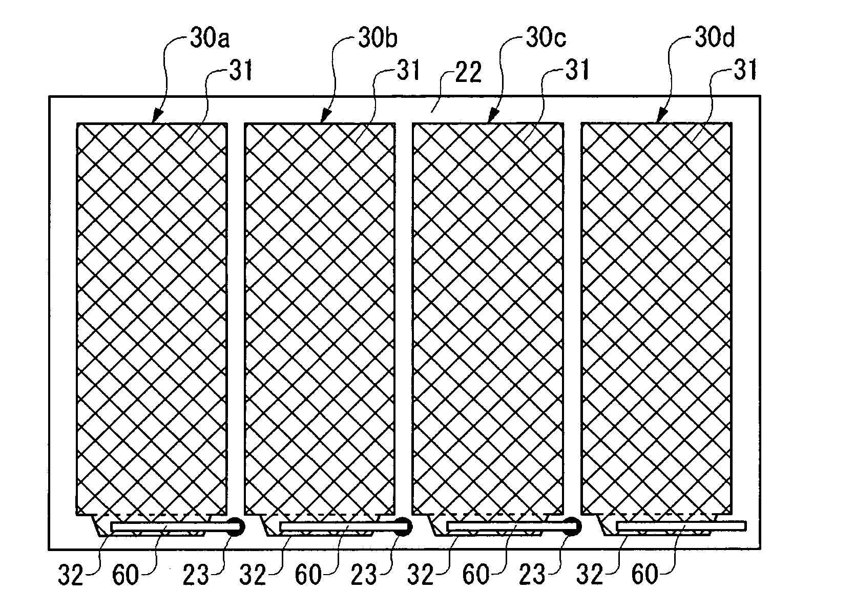
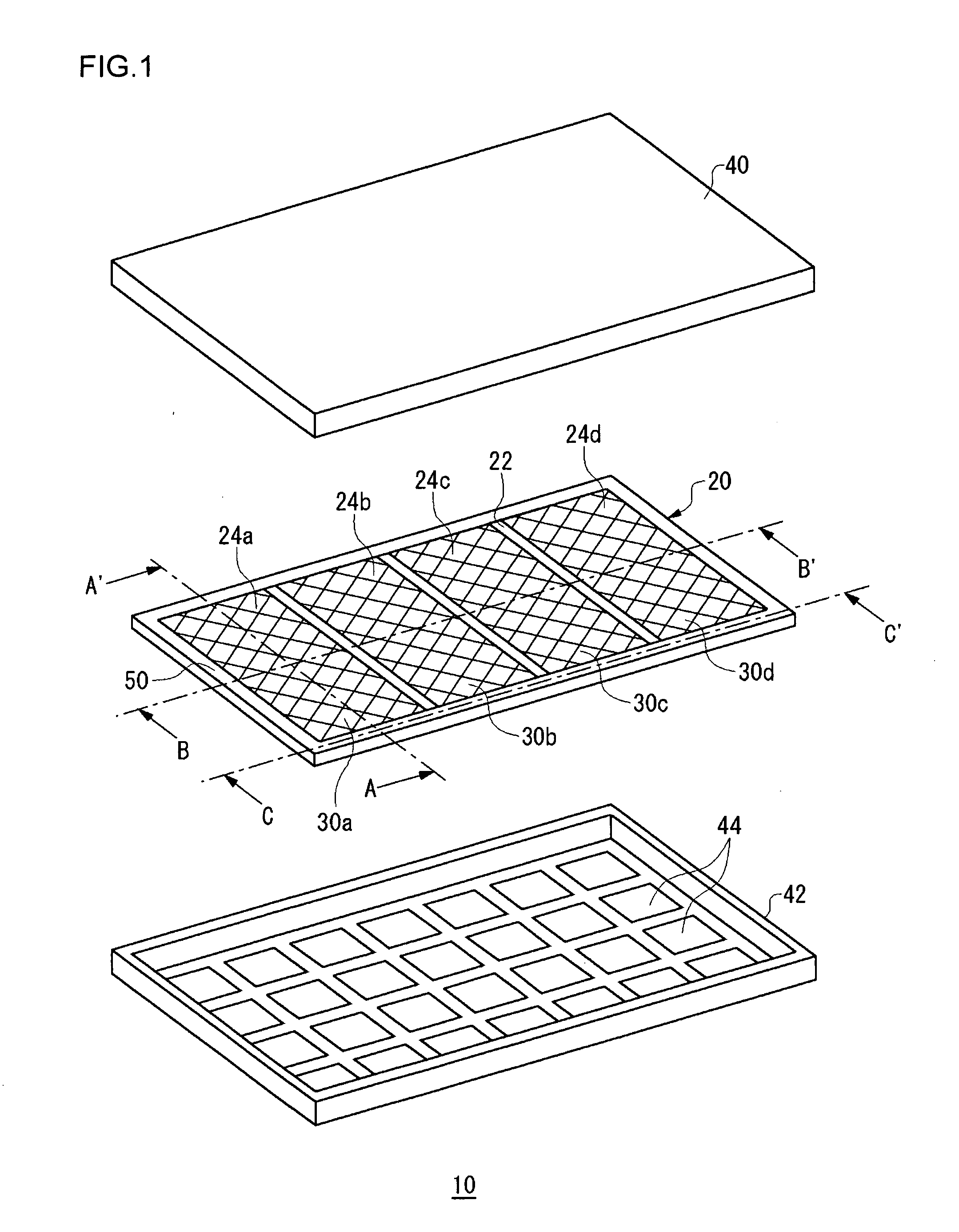
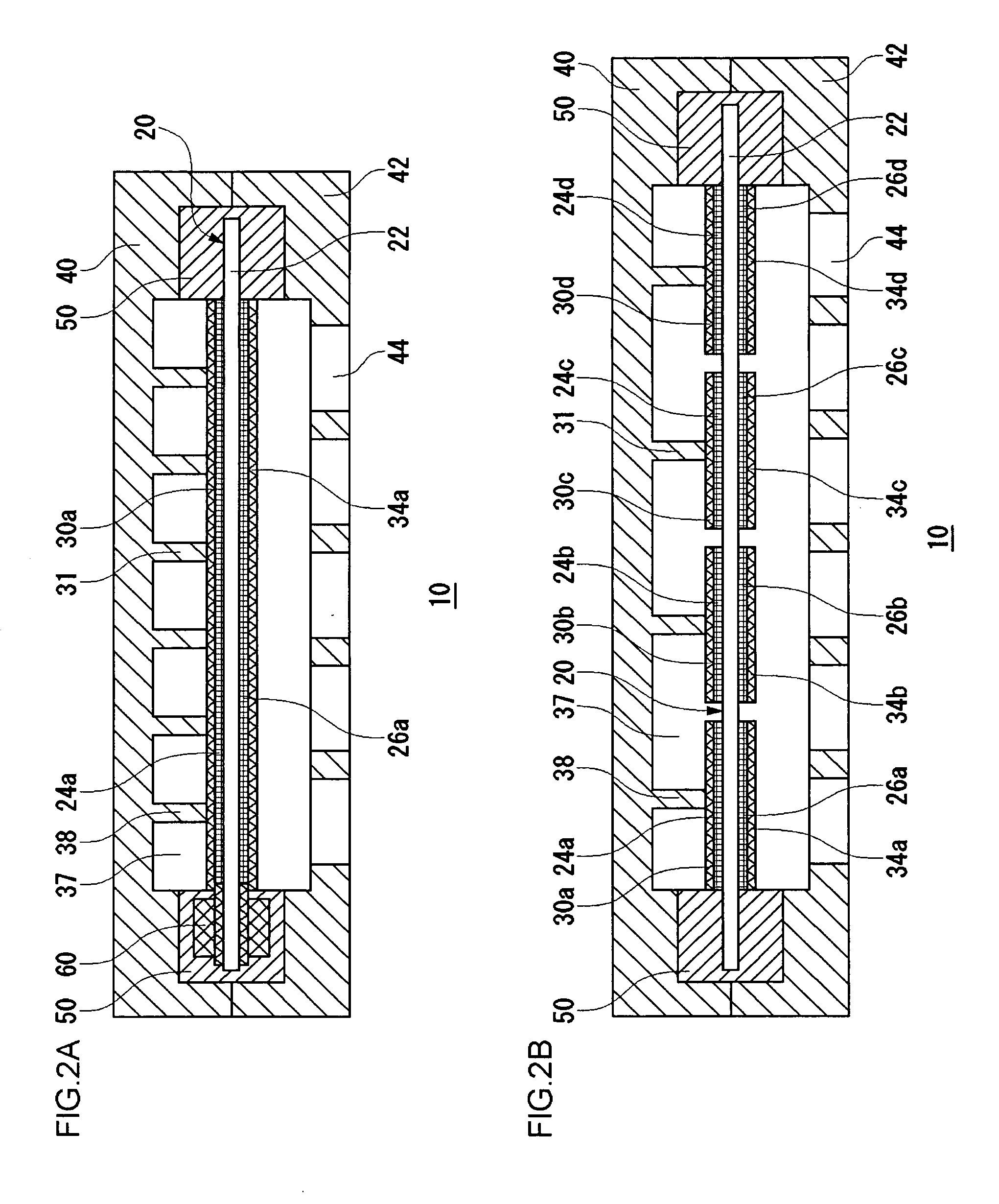
[0032]FIG. 1 is an exploded perspective view showing a structure of a fuel cell 10 according to an embodiment of the present invention. FIG. 2A and FIG. 2B are cross-sectional views taken along line A-A′ and the line B-B′ of FIG. 1, respectively. As illustrated in FIG. 1 and FIGS. 2A and 2B, the fuel cell 10 includes a membrane electrode assembly (MEA, also called a catalyst coated membrane (CCM)) 20, an anode housing 40, and a cathode housing 42. A sealing member 50 to be described later is provided around the peripheral edge part of the membrane electrode assembly 20.

[0033]The membrane electrode assembly 20 includes an electrolyte membrane 22, anodes 24a to 24d, and cathodes 26a to 26d, which are disposed c...


PUM

PropertyMeasurementUnit
Widthaaaaaaaaaa

Abstract

In a planar-array cell structure, an area required by interconnectors is reduced and a fuel cell is made further compact. A connection part which connects adjacent cells in series is provided within a sealing member provided in a peripheral edge part of an electrolyte membrane where multiple cells are formed in a planar arrangement. For each cell, an anode terminal of a current collector is disposed counter to a cathode terminal of the current collector via the electrolyte membrane. The connection part penetrates the electrolyte membrane and connects the anode terminal of one of the adjacent cells to the cathode terminal of the other of the adjacent cells.

Description

CROSS-REFERENCE TO RELATED APPLICATIONS[0001]This application is based upon and claims the benefit of priority from the prior Japanese Patent Application No. 2007-047984, filed on Feb. 27, 2007, the entire contents of which are incorporated herein by reference.BACKGROUND OF THE INVENTION[0002]1. Field of the Invention[0003]The present invention relates to a fuel cell. More particularly, the invention relates to a fuel cell with its cells disposed in a planar arrangement and a method for connecting current collectors thereto.[0004]2. Description of the Related Art[0005]A fuel cell is a device that generates electricity from hydrogen and oxygen so as to obtain highly efficient power generation. A principal feature of the fuel cell is its capacity for direct power generation which does not undergo a stage of thermal energy or kinetic energy as in the conventional power generation. This presents such advantages as high power generation efficiency despite the small scale setup, reduced e...

Claims


Application Information

Patent Timeline
IPC IPC(8): H01M8/10H01M2/08H01M8/00
CPCH01M8/241H01M2008/1095Y02E60/50Y10T29/49169H01M8/0247H01M8/0271H01M8/2418
Inventor IMURA, SHINICHIROYASUO, TAKASHI
Owner SANYO ELECTRIC CO LTD
Why Eureka
Try Eureka