
Transmission electron microscope

a technology of electron microscope and electron microscope, which is applied in the direction of material analysis using wave/particle radiation, instruments, nuclear engineering, etc., can solve the problems of limited sample size, difficult to map the distribution of protein structure, and single crystals that are difficult to map the molecular structure distribution, etc., and achieve high resolution

Inactive Publication Date: 2008-09-04
HITACHI LTD
View PDF12 Cites 17 Cited by
  • Summary
  • Abstract
  • Description
  • Claims
  • Application Information

AI Technical Summary

Benefits of technology

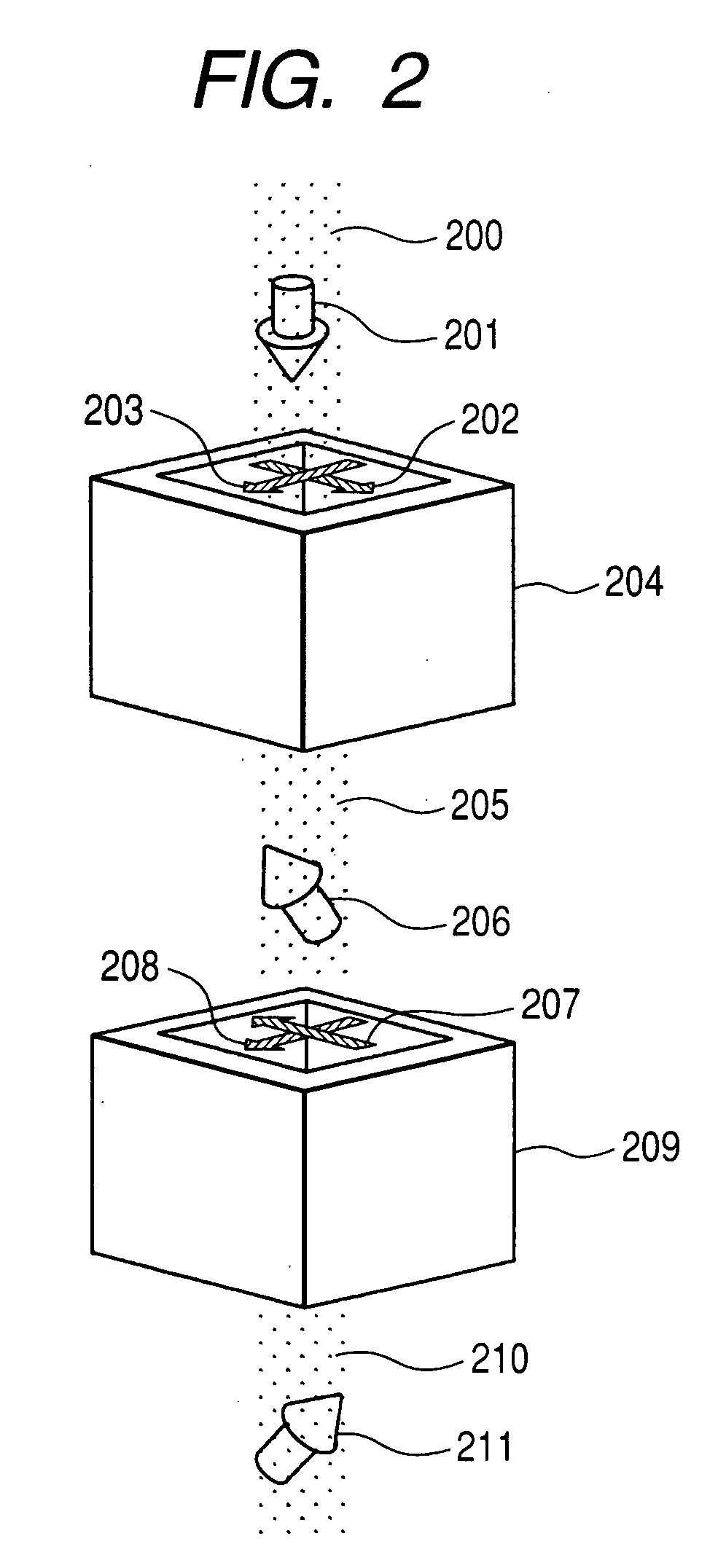
[0012]When electron beam holography measurement is performed in the above apparatus configuration, an interference pattern appears on the screen. In an ordinary electron beam holography apparatus, electric potential distribution, vector potential, and the like change the phase of an electron beam to cause a difference in interference pattern. Accordingly, in the case where there is no electric potential distribution or vector potential distribution, a uniform interference pattern appears in the ordinary electron beam holography. On the other hand, in the case of using an spin-polarized electron beam, assuming that the sample includes a portion with chirality structure and a portion without chirality structure, an electron beam that has passed through the portion with chirality structure causes a phase shift, which leads to an interference pattern shift. With the use of this method, the distribution of portions with chirality structure can be found based on information on portions where an interference pattern is shifted. Thus, it is an advantage of the invention to detect chirality in molecular structure which is completely different from physical quantities such as electric potential and vector potential that can detected by the ordinary electron beam holography. While the invention utilizes the phase difference of the spin-polarized electron beam, also the dichroism utilizing a transmittance difference is effective. However, in this method, the wavelength of an electron beam or light of a large difference in transmittance is limited depending on the sample; therefore, compared therewith, the method according to the invention utilizing the phase difference can be used for various purposes.
[0013]The amount of interference pattern shift is related to the thickness of the sample and the chirality structure in a film thickness direction, and also affected by the angle between the direction of a spin polarization vector and the symmetry axis of chirality. Accordingly, as the spin rotator changes the direction of the spin polarization, the amount of interference pattern shift changes. When data is acquired by thus changing the angle of the spin polarization vector with the spin rotator, findings about the direction of the symmetry axis of the chirality structure can be obtained.
[0014]A similar effect can be exerted on a magnetic sample. That is, the phase shift of the electron beam occurs depending on whether the spin polarization vector is parallel or antiparallel to the magnetization direction in the thin-film sample. Accordingly, in a holographic image, data in which the interference pattern is partially shifted depending on the magnetization direction can be acquired, thereby making it possible to analyze the magnetic domain structure. Particularly, in the case where the magnetization of the thin-film sample is perpendicular to the film, an ordinary transmission electron microscope such as the Lorentz microscope cannot detect the magnetization, whereas this method enables it. In this case as well, the amount of phase shift changes depending not only on the film thickness of the sample and the magnetization distribution in a film thickness direction, but also on the relationship between the spin polarization vector of the irradiating electron beam and the direction of magnetization of the sample. Accordingly, as the spin rotator changes the direction of the spin polarization, the amount of interference pattern shift changes. When data is acquired by thus changing the angle of the spin polarization vector with the spin rotator, findings about the direction of magnetization in the sample can be obtained.
[0015]As described above, with the use of the spin-polarized electron beam holography according to the invention, it is possible to provide an apparatus capable of mapping the chirality in the molecular structure of various samples and the magnetization of a magnetic thin film.
[0016]According to the invention, as described above, in analyzing the molecular structure of protein or the like, it is possible to provide means for achieving the mapping of an area of chirality with high resolution less than 10 nm. Further, it is possible to provide means for, with the resolution of a Lorentz microscope level, visualizing magnetization distribution, perpendicular to a sample film surface, which cannot be detected by the Lorentz microscope.

Problems solved by technology

In conventional X-ray diffraction, while data can be acquired with good resolution, it is basically impossible to map the distribution of molecular structure due to a single crystal.
However, in this case, there is a limit in sample size, with a restricted field of view.
Therefore, in current apparatuses, it is difficult to map the distribution of protein structure.
Therefore, in the case where an electron beam falls perpendicularly on the surface of a thin-film sample as in observation with an ordinary transmission electron microscope, it is difficult to detect the magnetization of a perpendicular magnetization film such as perpendicular magnetic recording on a hard disk.
Thus, in current apparatuses, it is difficult to perform high-resolution magnetic domain observation of a perpendicular magnetization film.
Further, a difference of transmission condition in the sample arises between left-handed circularly polarized light and right-handed circularly polarized light, which may cause a phase difference.
In this respect, the magnetic coil type is not suitable for the first one of the two spin rotators.

Method used


Image

  • Transmission electron microscope
  • Transmission electron microscope
  • Transmission electron microscope

Examples


first embodiment

[0027]Hereinafter, embodiments of the present invention will be described with reference to the accompanying drawings.

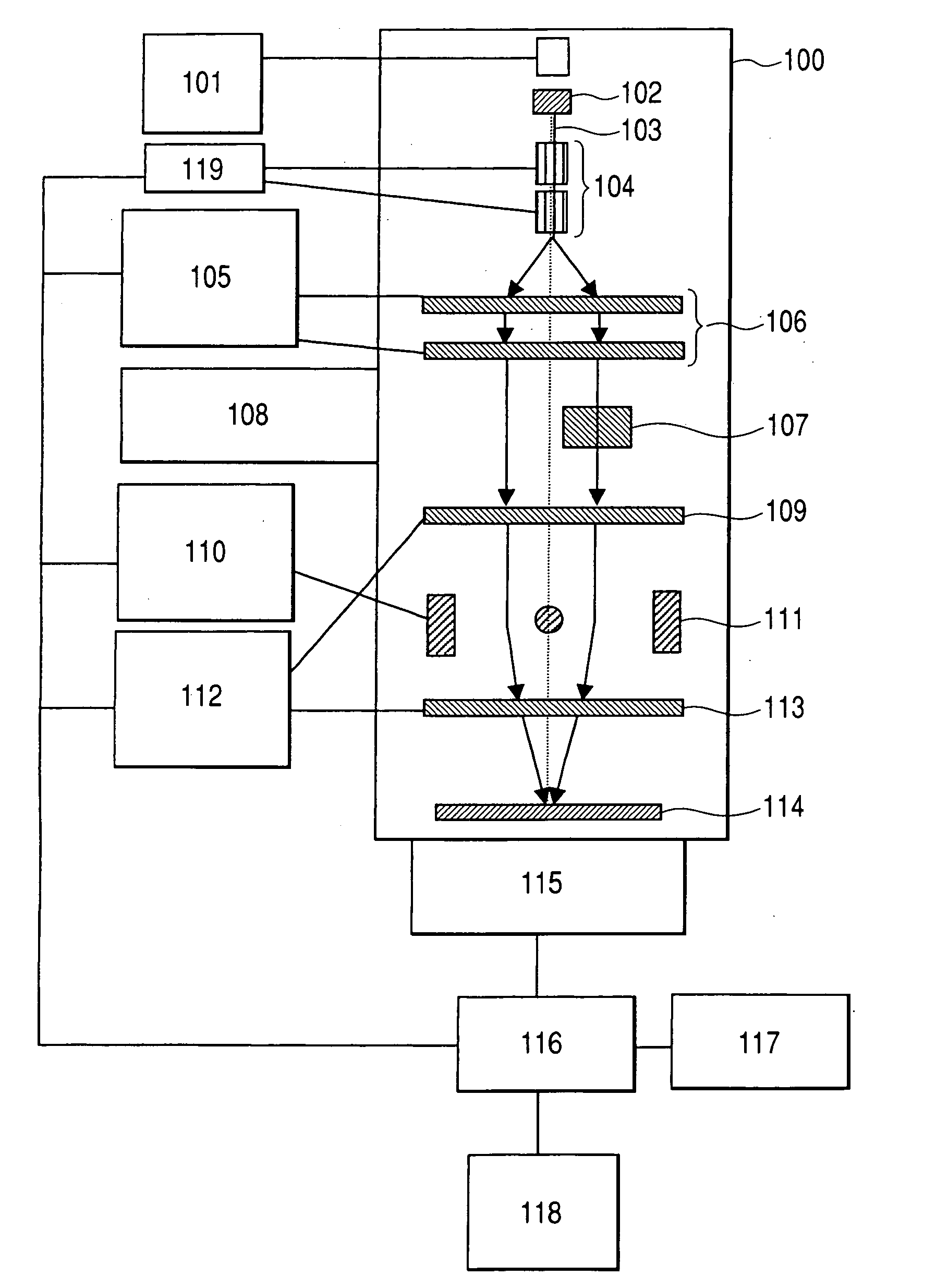
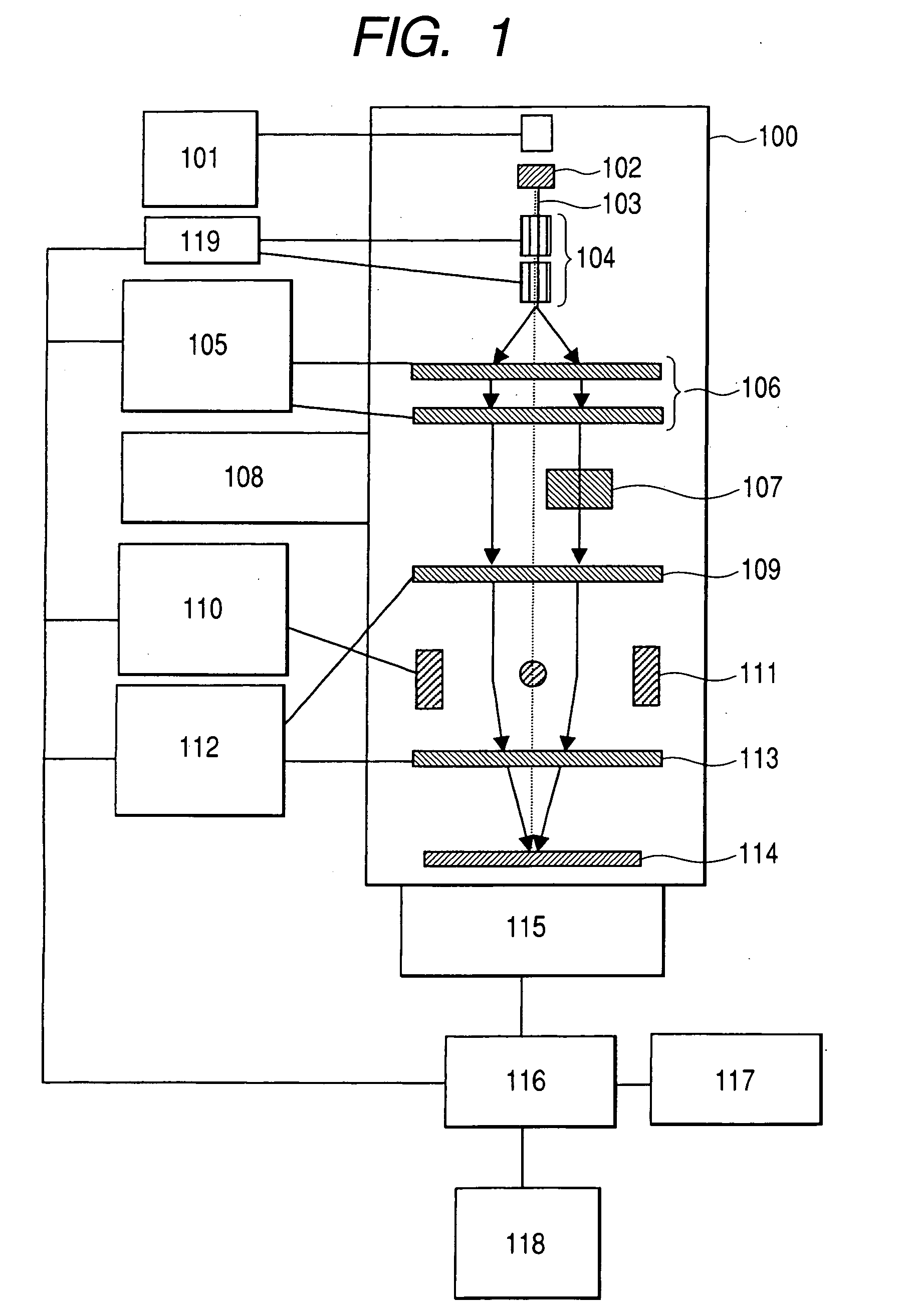
[0028]FIG. 1 shows a rough configuration of a spin-polarized electron beam holography apparatus according to the present invention. The entire apparatus is based on a transmission electron microscope, and is broadly divided into units incorporated in a vacuum chamber 100 and control units etc. in the air. A spin-polarized electron source 102 is controlled by a spin-polarized electron beam controller 101. For example, a type that excites a semiconductor such as GaAs with circularly polarized light may be used as the spin-polarized electron source 102, in which the wavelength of exciting light and the direction of circularly polarized light can be controlled by the spin-polarized electron beam controller 101. Emitted spin-polarized electrons are guided by a spin rotator 104 for adjustment of the angle. The strength of the spin rotator, that is, the magnitude and direct...


PUM

PropertyMeasurementUnit
crystal grain sizesaaaaaaaaaa
transmission electron microscopeaaaaaaaaaa
image processingaaaaaaaaaa

Abstract

Chirality distribution in the molecular structure of protein or the like and magnetic domain structure are analyzed with high resolution less than 10 nm. A transmission electron microscope equipped with a spin-polarized electron source is used for holography observation. The phase of transmission spin-polarized electrons changes due to the existence of chirality structure or magnetization in a sample, which is observed as an interference pattern phase shift in holography measurement.

Description

CLAIM OF PRIORITY[0001]The present application claims priority from Japanese application JP 2007-050921 filed on Mar. 1, 2007, the content of which is hereby incorporated by reference into this application.FIELD OF THE INVENTION[0002]The present invention relates to an apparatus for evaluating and analyzing the molecular structure of protein or the like or the magnetic domain structure of a magnetic substance.BACKGROUND OF THE INVENTION[0003]There has been much demand for analysis of the structures of high molecular compounds typified by protein, with advanced requests. That is, there have been many studies for analyzing the nature and function of protein as well as its structure and utilizing the results for medical and pharmaceutical sciences. X-ray diffraction is best known as a method of analyzing protein microstructure. X-ray diffraction requires the creation of a single crystal sample but enables high-resolution measurement, which is described for example in Medical Tribune (V...

Claims


Application Information

Patent Timeline
Patent Type & Authority Applications(United States)
IPC IPC(8): G01N23/00
CPCH01J37/265H01J37/266H01J2237/06383H01J2237/2614H01J2237/24557H01J2237/2588H01J2237/1514
Inventor KOHASHI, TERUOOHSHIMA, TAKASHIMATSUMOTO, TAKAONISHIDA, HIROKAZU
Owner HITACHI LTD
Learn More