[0076]With the above arrangement, it is possible to obtain the same advantageous effects as provided by the above-described embodiment. Further, although in the above-described
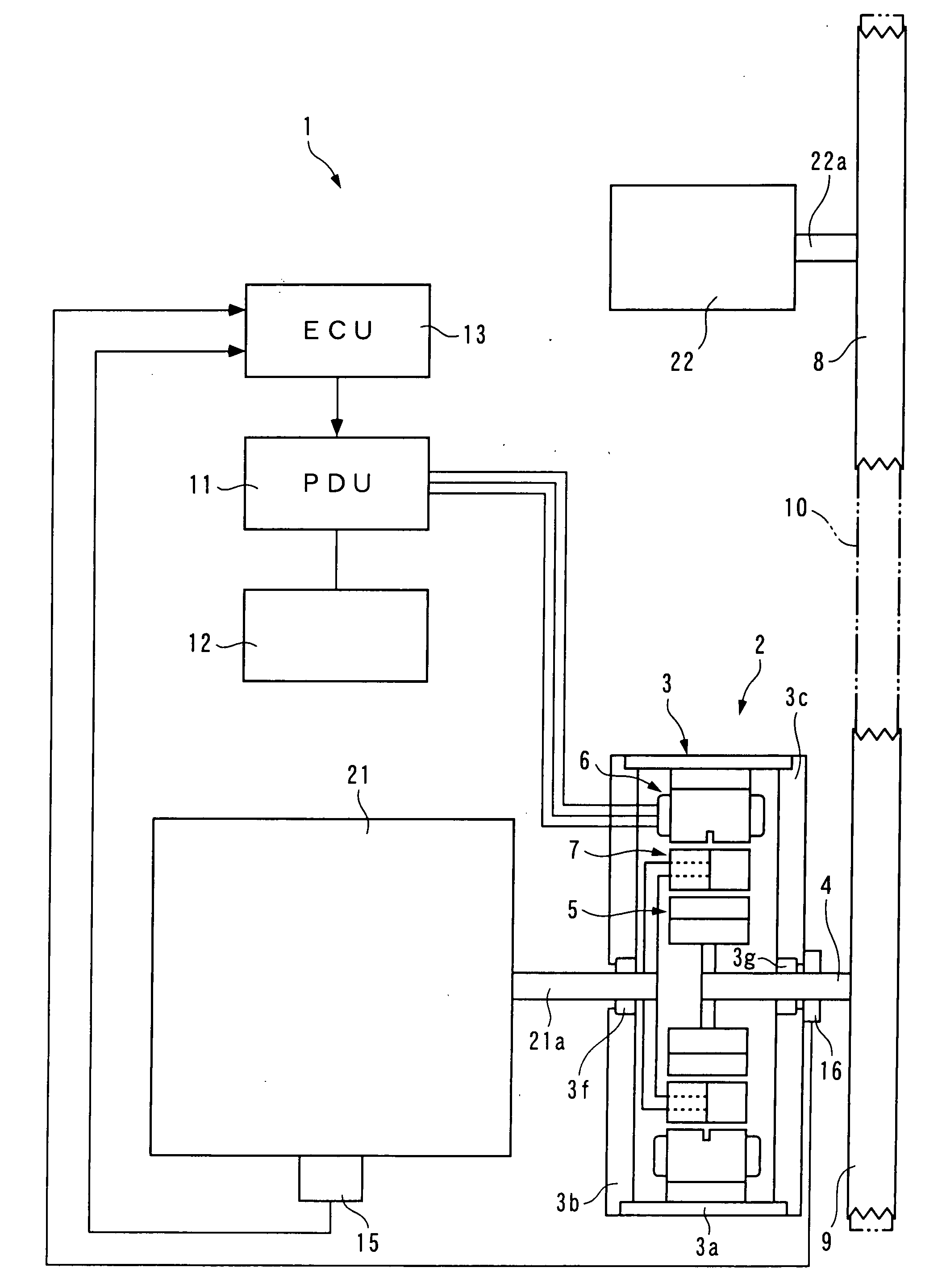
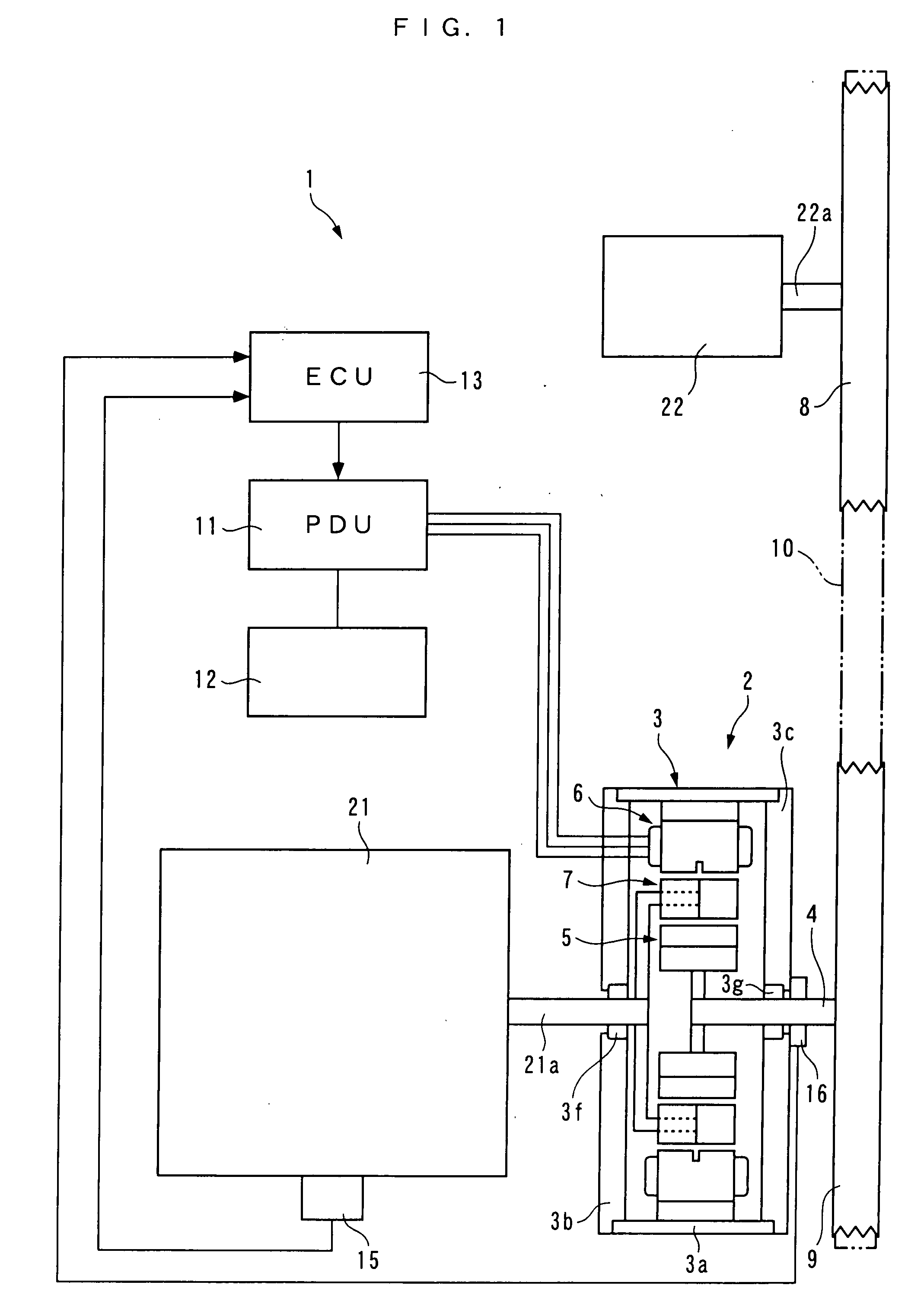
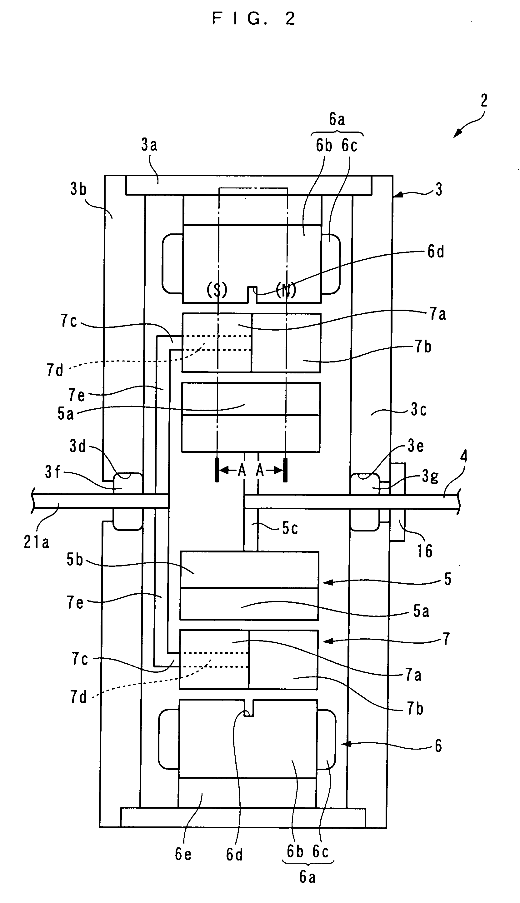
power transmission drive system 2, the output pulley 9 is provided separately from the
stator 6 and so forth, in the
power transmission drive system 2A, the first rotor 5, the
stator 6, and the second rotor 7 are arranged within the pulley 9A, so that it is possible to further downsize the accessory drive system 1.
[0077]Next, a second variation of the above-described embodiment will be described with reference to FIG. 10. As shown in the figure, in the second variation, a
power transmission drive system 2B is mainly distinguished from the power transmission drive system 2 in that it is directly connected to an accessory 23 without using a pulley or a belt. The accessory 23 is an
oil pump, for example. More specifically, the fixing portion 5b of the first rotor 5 is directly connected to an input shaft 23a of the accessory 23 by a hollow cylindrical connecting portion 5i. The input shaft 23a is formed to be hollow, and is rotatably supported by a bearing 3f. The
crankshaft 21a is concentrically rotatably fitted in the input shaft 23a.
[0078]With the above arrangement, it is possible to obtain the same advantageous effects as provided by the above-described embodiment. Further, compared with the above-described embodiment, since the input and output pulleys 8 and 9, and the belt 10 are omitted, it is possible to still further downsize the accessory drive system 1 and reduce manufacturing costs thereof, accordingly.
[0079]Next, a third variation of the above-described embodiment will be described with reference to FIG. 11. In the third variation variation, a power transmission drive system 2C is distinguished from the power transmission drive system 2 only in that the first rotor 5 and the second rotor 7 are connected to the crankshaft 21a and the accessory 22, respectively. Hereinafter, a description will be given of the operation of the power transmission drive system 2C.
[0080]First, a description will be given of the operation of the power transmission drive system 2C during stoppage of the engine 21. In this case, the friction of the engine 21 acts on the first rotor 5, that is, the permanent magnets 5a. Since the friction is by far larger than torque required for driving the accessory 22, the permanent magnets 5a are in a substantially unrotatable state. In such a state, the ECU 13 controls the PDU 11 to thereby supply the stator 6 with
electric power to generate the first and second rotating magnetic fields, whereby the output shaft 4 integrally formed with the second rotor 7 is rotated to drive the accessory 22.
[0081]It should be noted that the operation of the power transmission drive system 2C is described by assuming that similarly to the above-described embodiment, the permanent magnets 5a, the armatures 6a, and the first and second cores 7a and 7b are arranged as shown in FIG. 4, and by replacing the motion of the first and second rotating magnetic fields by physical motions of imaginary permanent magnets VM equivalent thereto. Further, in this case as well, the description will be given assuming that the magnetic pole on the left-side portion of the imaginary
magnet VM (on the first magnetic pole side), and the magnetic pole on the right-side portion of the imaginary
magnet VM (on the second magnetic pole side) are regarded as the first and second armature
magnetic poles, respectively, and that the rotating magnetic fields generated between the left-side portion of the imaginary
magnet VM and the left portion of the first rotor 5 (on the first magnetic pole side), and between the right-side portion of the imaginary magnet VM and the right portion of the first rotor 5 (on the second magnetic pole side) are regarded as the first and second rotating magnetic fields. Furthermore, hereinafter, the left portion and the right portion of the permanent magnet 5a are referred to as “the first magnet portion” and “the second magnet portion”.

