Frequency Controller Resonant Converter

a frequency controller and resonant converter technology, applied in the direction of electric variable regulation, process and machine control, instruments, etc., can solve the problems of high cost of implementation, unsatisfactory frequency shifts, and significant reduction of system power transfer capacity

Active Publication Date: 2008-09-04
AUCKLAND UNISERVICES LTD
View PDF16 Cites 74 Cited by
  • Summary
  • Abstract
  • Description
  • Claims
  • Application Information

AI Technical Summary

Benefits of technology

[0010]It is an object of the present invention to provide a resonant converter which will overcome disadvantages associated with existing constructions, or which will at least provide a useful alternative.

Problems solved by technology

In these and other applications of resonant converters, undesirable frequency shifts can occur, which are subject to load or circuit parameter variations.
These can result in significant reduction of system power transfer capacity.
These problems can be overcome, but this requires complex design which is expensive to implement, such as third generation (G3) power supplies using complicated LC converting networks.
One example of the difficulties created by frequency shifts is resonant converter power supplies in ICPT systems.
This frequency drift in turn has an adverse effect on the pick-ups because the tuning capacitor for each pick-up tunes the pick-up coil to the resonant frequency of the converter.
As the converter resonant frequency drifts away, the power transferred to the pick-ups decreases, so the system becomes inefficient.
This is particularly disadvantageous with high Q systems since many separate capacitors are required, adding to cost and complexity.
It also means that load variations have to be limited to make the system function effectively.

Method used


Image

  • Frequency Controller Resonant Converter
  • Frequency Controller Resonant Converter
  • Frequency Controller Resonant Converter

Examples


Embodiment Construction

)

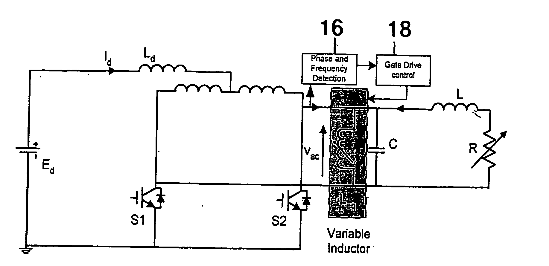
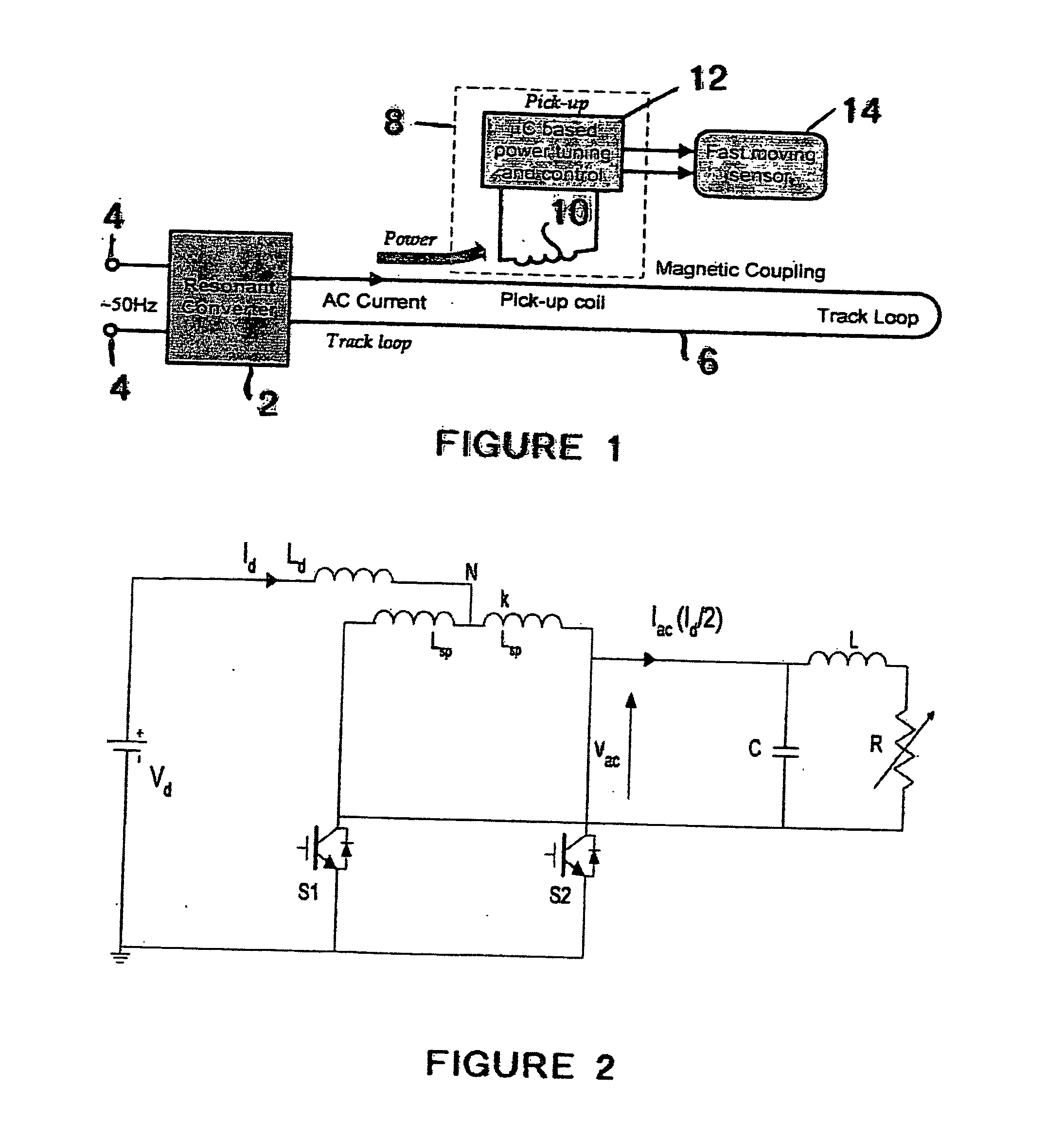
[0042]Referring to FIG. 1, the basic structure of an inductively coupled power transfer (ICPT) system is shown. Such a supply is also often referred to as a contactless power supply system. The system generally comprises two electrically isolated parts. The first part consists of a power supply such as a resonant converter 2 which has inputs 4 for connection to a source of electrical energy. In this example the inputs 4 may be connected to a 50 Hz mains supply. The first part also includes a primary conductive path 6 which is supplied with alternating current from the resonant converter 2. The primary conductive path 6 is usually in the form of an elongated “track” or cable along which one or more of the second parts are located. However, the primary conductive path 6 may comprise a coil of conductive material. In this example, the main function of the converter is to supply a nominally constant high frequency (e.g. 40 kHz) AC current in the track loop.

[0043]The second part consist...


PUM

PropertyMeasurementUnit
frequencyaaaaaaaaaa
frequenciesaaaaaaaaaa
delay angleaaaaaaaaaa

Abstract

A resonant converter is provided which may be used for supplying power to the primary conductive path of an inductively coupled power transfer (ICPT) system. The converter includes a variable reactive element in the resonant circuit which may be controlled to vary the effective inductance or capacitance of the reactive element. The frequency of the converter is stabilised to a nominal value by sensing the frequency of the converter resonant circuit, comparing the sensed frequency with a nominal frequency and varying the effective inductance or capacitance of the variable reactive element to adjust the converter frequency toward the nominal frequency.

Description

FIELD OF THE INVENTION[0001]This invention relates to resonant converters. The invention has particular application to Inductively Coupled Power Transfer (ICPT) power supplies, but the invention is not limited to this application.BACKGROUND[0002]Converters are widely used for various power conversion and control applications, including converting sources of direct current (DC) electrical energy into alternating current (AC) power supplies. In particular, current-fed resonant converters are widely used for various DC and AC powers supplies, due to their efficient and compact features.[0003]A successful application of current-fed resonant converters is in Inductively Coupled Power Transfer (ICPT) systems. Other applications include induction heating.[0004]In these and other applications of resonant converters, undesirable frequency shifts can occur, which are subject to load or circuit parameter variations. These can result in significant reduction of system power transfer capacity.[0...

Claims


Application Information

Patent Timeline
Patent Type & Authority Applications(United States)
IPC IPC(8): H01F21/00H02J1/00H02M1/00H02M3/337H02M7/217H02M7/48
CPCH02J1/00H02J2001/002H02M3/3374H02M7/217Y02B70/1441H02M2007/4815H02M2007/4818Y02B70/1433H02M2001/008H02J50/12H02J1/002H02J1/08Y02B70/10H02M1/008H02M7/4818H02M7/4815
Inventor HUSSMAN, STEPHAN H.HU, AIGUO
Owner AUCKLAND UNISERVICES LTD
Why Eureka
Try Eureka