Porous Photonic Crystal with Light Scattering Domains and Methods of Synthesis and Use Thereof

a photonic crystal and light scattering technology, applied in the field of optical nanostructures and optical nanostructure synthesis, can solve the problem that the changes in cellular physiology cannot be readily converted into electronic signals in real-time, and achieve the effect of increasing scattering efficiency and being easy to solv

Inactive Publication Date: 2008-09-04
RGT UNIV OF CALIFORNIA
View PDF31 Cites 12 Cited by
  • Summary
  • Abstract
  • Description
  • Claims
  • Application Information

AI Technical Summary

Benefits of technology

[0012]FIG. 5b is a microscope image of hepatocytes after exposure to 200 mM Cd2+. Scattering efficiency increases as the hepatocytes lose viability, and cellular features such as nuclei can be easily resolved.

Problems solved by technology

However, many biological events that signal changes in cellular physiology cannot readily be converted into an electronic signal in real-time.

Method used


Image

  • Porous Photonic Crystal with Light Scattering Domains and Methods of Synthesis and Use Thereof
  • Porous Photonic Crystal with Light Scattering Domains and Methods of Synthesis and Use Thereof
  • Porous Photonic Crystal with Light Scattering Domains and Methods of Synthesis and Use Thereof

Examples


Embodiment Construction

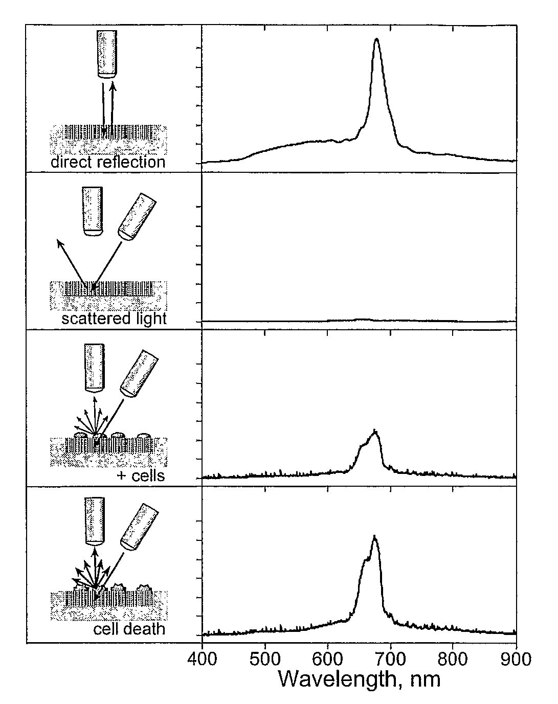
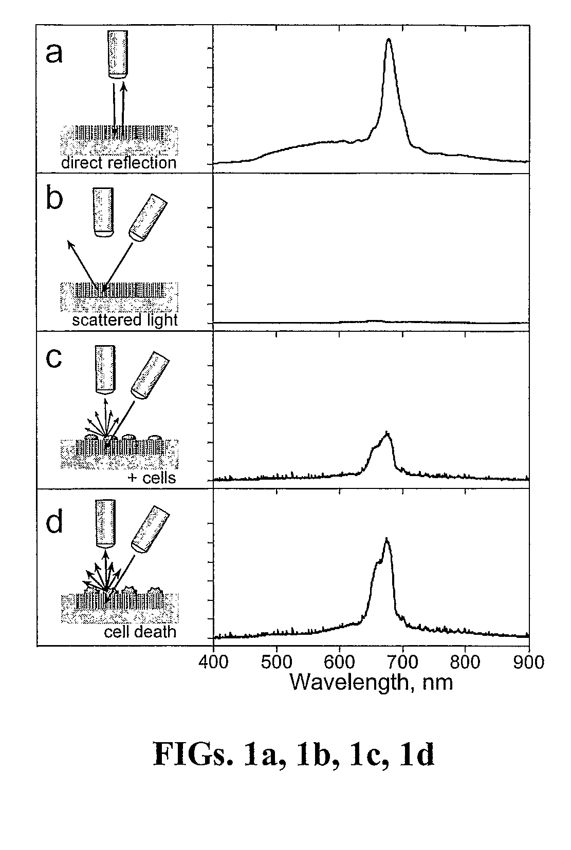
[0026]The invention exploits a scattering phenomenon whereby the intensity and / or the color of scattered light impinged on a porous or photonic substrate changes as a result of physiological changes in the cells overlaying the substrate. The intensity changes occur based on morphological changes in the cells that affect the efficiency of the scattering process. The color changes occur when substances, such as cells or molecules excreted by cells, enter the pores of the substrate. More specifically, the invention includes a porous or photonic substrate having a well-defined and highly tunable color, such as porous silicon (Si), porous alumina, porous Ge, porous GaAs, porous SiO2 and porous polymer, for example. The porous substrate or cells seeded on a porous substrate are exposed to an analyte, a toxin, a virus, or other macromolecule that can affect cellular physiology, and changes in the scattered light are observed over time to determine cell morphology on and / or chemical composi...


PUM

PropertyMeasurementUnit
wavelengthaaaaaaaaaa
thicknessaaaaaaaaaa
current densityaaaaaaaaaa

Abstract

The invention includes sensors and sensing methods for determining cell morphology and/or chemical composition of an analyte. A porous substrate exhibiting a first optical signal is exposed to a target analyte and subsequently monitored for changes in the optical signal. More specifically, a photonic or porous substrate having a well-defined and highly tunable reflectivity or transmission spectrum, such as porous silicon (Si), porous alumina, porous Ge, porous GaAs, porous SiO2 and porous polymer, is used for example. A porous or photonic substrate is exposed to an analyte, such as a cell or other macromolecule, and changes in the scattered light are observed over time to determine cell morphology and/or chemical composition of the analyte using the substrate.

Description

TECHNICAL FIELD[0001]The instant invention is directed to optical nanostructures, the synthesis of optical nanostructures, and the use of optical nanostructures in sensing applications.BACKGROUND OF THE INVENTION[0002]Detection, analysis and quantification of an analyte, such as a cell, macromolecule, protein, polymer, biomolecule, biopolymer or other molecular complex has widespread application in fields such as genomics, proteomics, drug discovery, medical diagnostics, environmental sensing, pollution monitoring, detection of chemical or biological warfare agents, and industrial process monitoring. For example, cell and tissue-based biosensors are useful for many medical, pharmaceutical, and environmental applications. One significant advantage of using living elements in sensors is that, in principle, complex biological interactions can be monitored. However, many biological events that signal changes in cellular physiology cannot readily be converted into an electronic signal in...

Claims


Application Information

Patent Timeline
Patent Type & Authority Applications(United States)
IPC IPC(8): G01N1/00
CPCG01N21/4738G01N33/54373G01N33/5005
Inventor SAILOR, MICHAEL J.SCHWARTZ, MICHAEL P.ALVAREZ, SARABHATIA, SANGEETADERFUS, AUSTINMIGLIORI, BENJAMINCHAO, LINLI, YANG YANGCAMPBELL, REBECCADORVEE, JASONRANG, ULLA CAMILLA
Owner RGT UNIV OF CALIFORNIA
Why Eureka
Try Eureka