Sealing element for use in a fluid-flow machine

Active Publication Date: 2008-09-04
ANSALDO ENERGIA SWITZERLAND AG
View PDF7 Cites 16 Cited by
  • Summary
  • Abstract
  • Description
  • Claims
  • Application Information

AI Technical Summary

Benefits of technology

[0011]An object of the present invention is to provide a sealing element, a sealing arrangement and a fluid-flow machine with which one or more disadvantages of the prior art are reduced or avoided. In particular, the present invention provides a sealing element for sealing component gaps th

Problems solved by technology

In fluid-flow machines, such as in gas or steam turbines for example, component gaps cause the formation of bleed or leakage flows.
Bleed or leakage flows are generally undesired, since they no longer provide any contribution to the energy conversion and consequently, as a loss of the main flow, have to be balanced.
Furthermore, in particular downstream of a combustion chamber, the working fluid is very hot.
Bleed or leakage flows which originate from this hot flow are accordingly similarly very hot and ca

Method used


Image

  • Sealing element for use in a fluid-flow machine
  • Sealing element for use in a fluid-flow machine
  • Sealing element for use in a fluid-flow machine

Examples


Example

[0046]In the figures, only elements and components that are essential for the understanding of the invention are represented. The exemplary embodiment represented is to be understood as being purely instructive and is intended to serve for better understanding but not for restricting the subject matter of the invention.

DETAILED DESCRIPTION

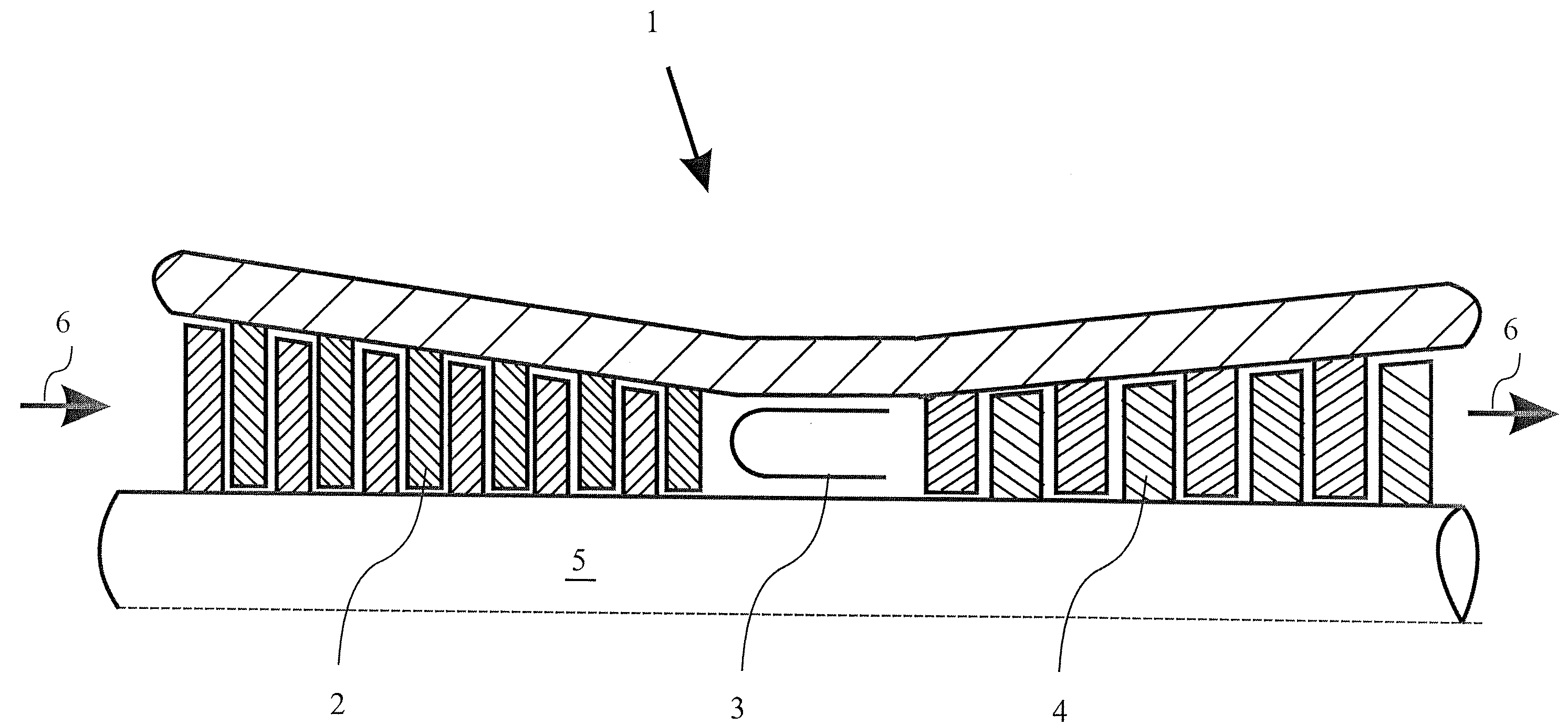
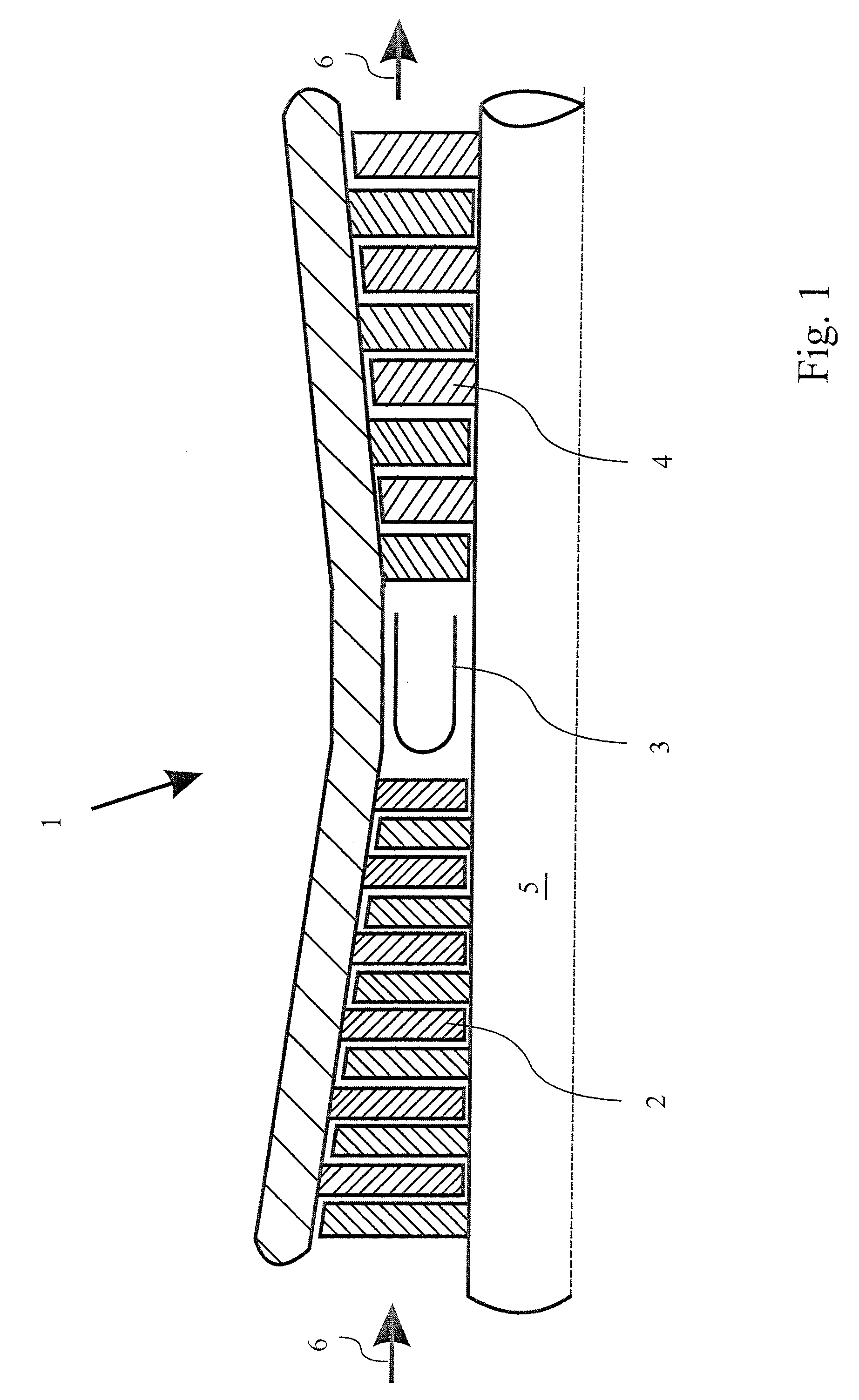
[0047]In FIG. 1, a gas turbine 1 known from the prior art is represented in a schematized representation. Such gas turbines are used for example in power generating plants for generating electric power and represent a typical area of application of the invention. The sealing element formed according to the invention may, however, also be used in fluid-flow machines used in other ways, such as for example in fluid-flow machines which are used in process plants or for generating propulsive power.

[0048]The gas turbine 1 comprises as essential components, represented in FIG. 1, a compressor 2, a combustion chamber 3 and a turbine 4. The compressor 2 a...


PUM


Abstract

A sealing element for sealing a component gap with respect to a flow, in particular for use in a fluid-flow machine, specifically in a turbomachine is provided. In addition a fluid-flow machine is provided including such a sealing element for sealing a component gap. The sealing element includes a hollow profile enclosing a cavity. Arranged in the hollow profile are a first opening and a second opening, which are spaced apart from each other in the longitudinal direction of the hollow profile. The first opening is formed as an inlet opening for a cooling fluid into the cavity of the hollow profile, the second opening is formed as an outlet opening for the cooling fluid from the cavity of the hollow profile. With the sealing element arranged in a fluid-flow machine, the sealing element can consequently be internally cooled by means of the cooling fluid. Furthermore, the sealing element uses the pressure gradient occurring in the flow in the direction of flow to form a stable cooling fluid flow.

Description

[0001]This application is a continuation of International Patent Application No. PCT / EP2006 / 050629, filed on Feb. 2, 2006, which claims priority to Swiss Patent Application No. CH 258 / 05, filed on Feb. 15, 2005. The entire disclosure of both applications is incorporated by reference herein.[0002]The present invention relates to a sealing element for sealing a component gap with respect to a flow, in particular for use in a fluid-flow machine, specifically in a turbomachine. Furthermore, the invention relates to a fluid-flow machine in which such a sealing element is arranged for sealing a component gap.BACKGROUND[0003]In fluid-flow machines, such as in gas or steam turbines for example, component gaps cause the formation of bleed or leakage flows. This involves part of the working fluid of the main flow, which flows along a flow channel through the fluid-flow machine, penetrating into the component gaps adjacent the flow channel and escaping via these component gaps. Such component ...

Claims


Application Information

Patent Timeline
IPC IPC(8): F01D11/08
CPCF01D11/005F16J15/027Y10S277/93F05D2260/20F16J15/0893
Inventor JOHNSON CAMPINO, NICOLASHURTER, JONASSTEMANN, MARKUSTRIFONOV, SERGEYZAGORSKIY, ALEXANDER
Owner ANSALDO ENERGIA SWITZERLAND AG
Why Eureka
Try Eureka