Flame detector

a detector and flame technology, applied in the field of flame detectors, can solve the problems of relatively large detection limits of sulfur and phosphorus, relative few have been adapted to micro-analytical formats, etc., and achieve the effects of promoting chemiluminescence and photometric detection, sufficient melting point, and high melting poin

Inactive Publication Date: 2008-09-04
UTI LLP
View PDF5 Cites 20 Cited by
  • Summary
  • Abstract
  • Description
  • Claims
  • Application Information

AI Technical Summary

Benefits of technology

[0006]A flame detector is described in the parent application, which is U.S. Application Publication No. 2005/0287033 published Dec. 29, 2005 (the '033 Publication), in which a micro-flame detector is provided comprising a housing having an oxygen inlet, a hydrogen inlet, an analyte port and a flame region. A metal capillary delivers oxygen through the oxygen inlet to the flame region. The metal capillary has a melting point sufficiently high that glow emissions from the metal capillary during flame detection does not significantly interfere with detection. A hydrogen and analyte delivery system delivers hydrogen and analyte to the flame region. The flame detector may be operated in a photometric mode in which a photo-detector is arranged to detect flame emission through a flame detection port or an ionization mode in which an ionization detector is arranged to detect flame characteristics. In an embodiment, the metal capillary provides a flame stabilization surface for a flame less than 1 μL in volume. In another embodiment, the metal capillary is a stainless steel capillary. The hydrogen and oxygen may be provided in a countercurrent mode.
[0007]The results reported in the '033 publication for the μFID were generated as a by-product of the hydrogen-rich flame conditions designed to promote chemiluminescence and photometric detection of target analytes in the μFPD. The μFID may be used as an independent detector for use in GC. For example, the μFID may be operated inside the end of a capillary GC column. Sub...

Problems solved by technology

Although flame-based detectors are prevalent in many conventional GC applications, relatively few have been adapted to micro-analytical formats.
Since the latter tend to utilize very small (nL range) channels, this may be partly attributed to difficulties encountered in...

Method used


Image

  • Flame detector
  • Flame detector
  • Flame detector

Examples


Embodiment Construction

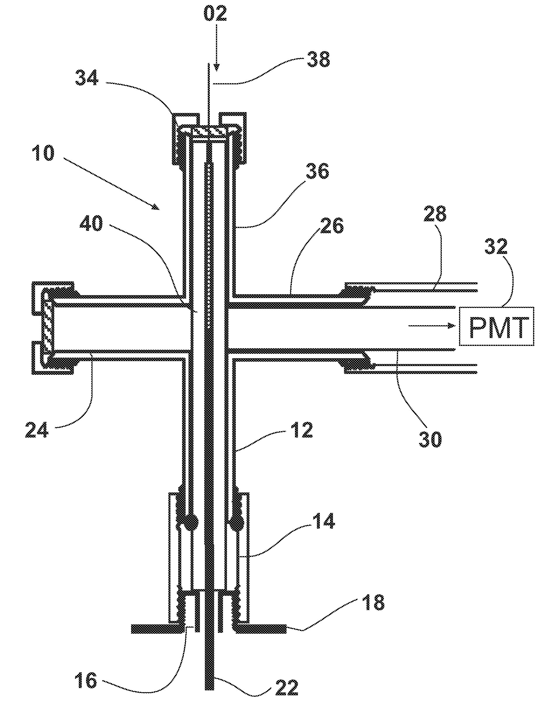
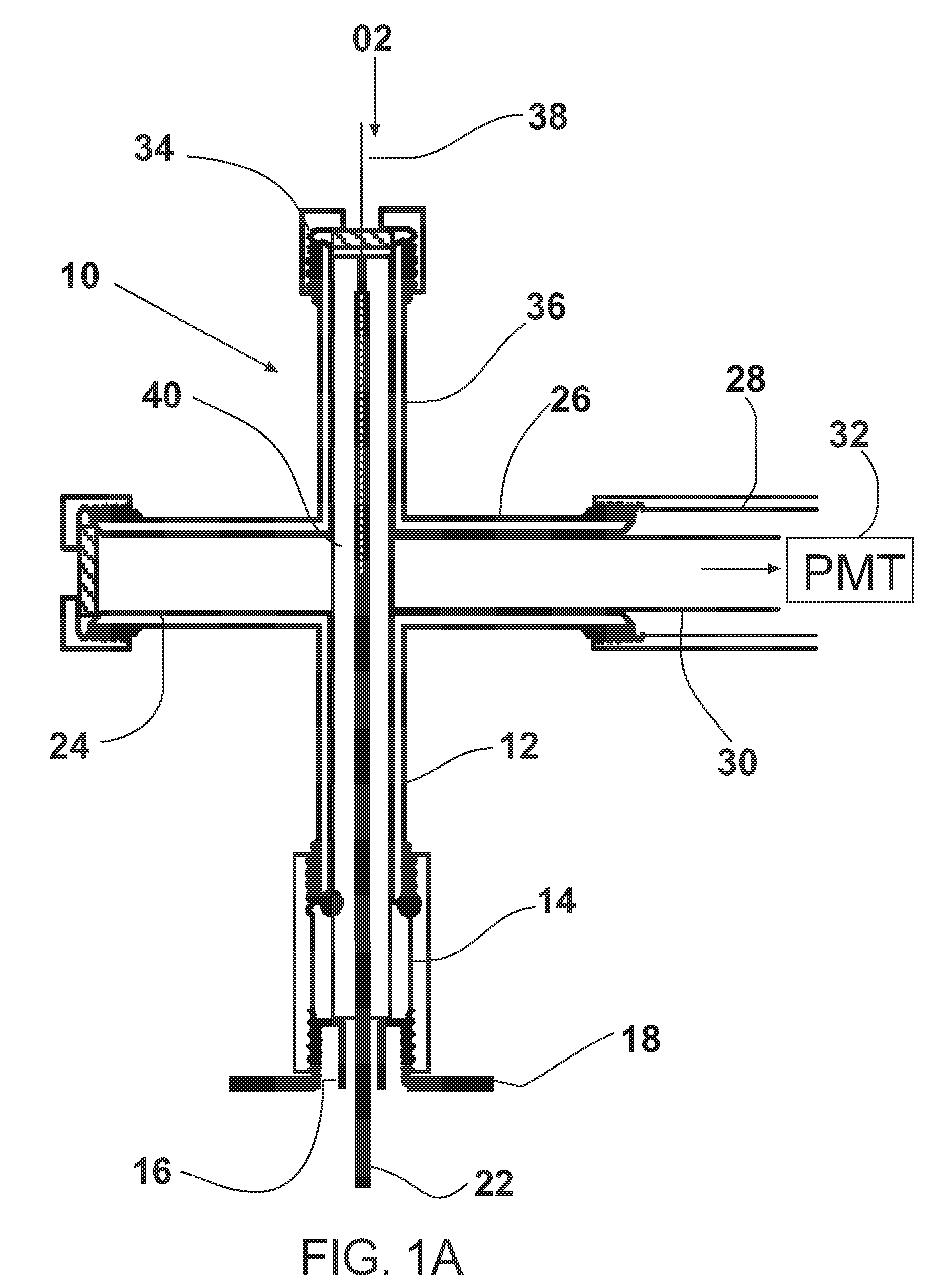
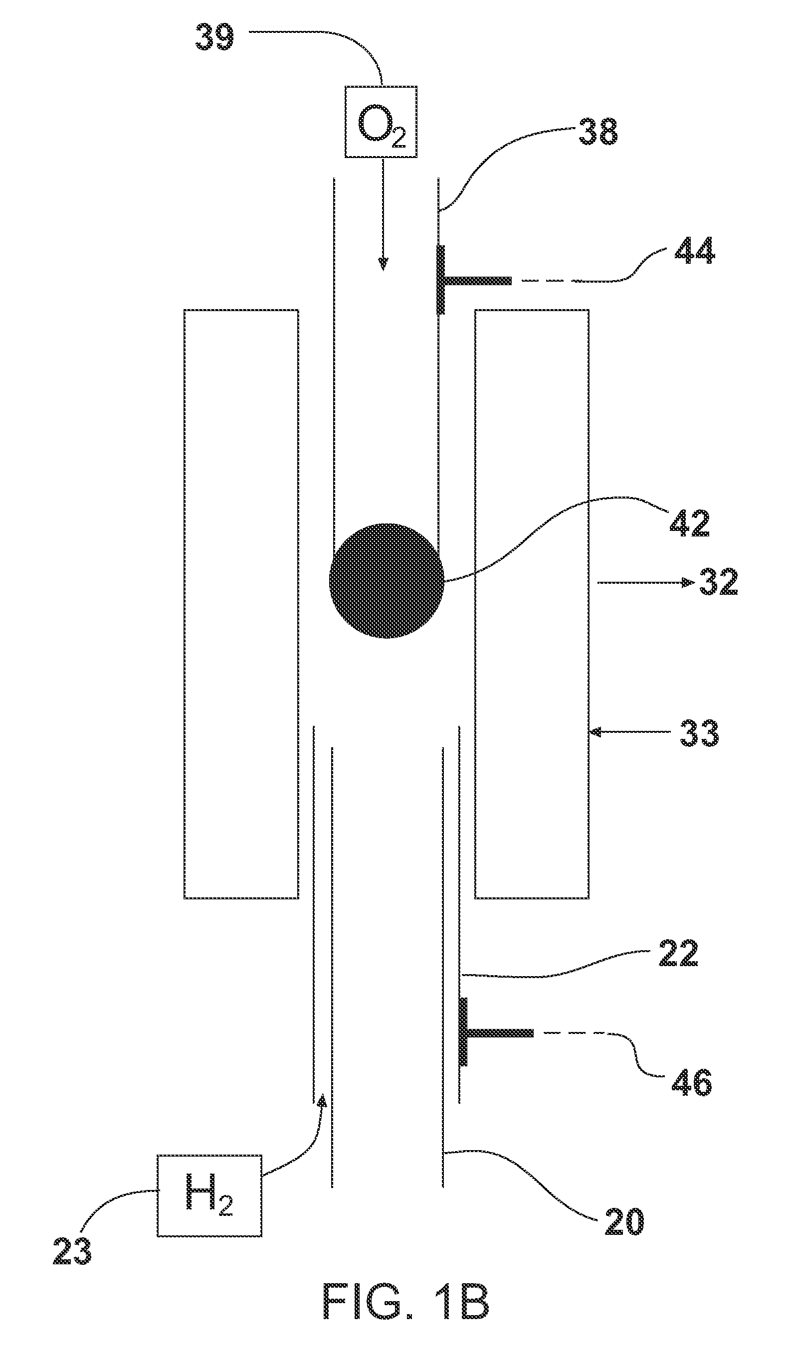
[0018]In this patent document, the word “comprising” does not exclude other elements being present and the use of the indefinite article “a” before an element does not exclude others of the same element being present. A flame photometric detector is considered to be a micro-flame detector, either μFID (ionization detector) or μFPD (photometric detector), if the flame volume, as defined by the visible boundary of the flame, is less than 1 μL (1×10⁻⁶ L), which for example is satisfied by spherical flame diameters of less than 1 mm. In particular, the μFPD shown in FIGS. 1A and 1B for which experimental results are described here produces a flame of approximately 30 nL in volume.

[0019]A micro-flame detector arranged for counter-current operation comprises a first tube connected to an oxygen source that provides a flow path for oxygen towards a flame region and a second tube connected to a hydrogen source that provides a flow path for hydrogen towards the flame region, the flows being o...


PUM


Abstract

Improved operating modes of a micro counter-current flame ionization detector (μFID) are demonstrated. By operating the flame inside the end of a capillary gas chromatography (GC) column, the effective cell volume enclosing the flame is considerably reduced and results in significantly lower gas flows being required to produce optimal sensitivity from the stable flame. In a post-column μFID arrangement, a very lean flame is now situated on the end of a stainless steel capillary delivering 10 mL/min of hydrogen, which is opposed by a counter-current flow of only 20 mL/min of oxygen. The μFID detection limit obtained in this stable, oxygen-rich counter-current flame mode is 7×10⁻¹¹ gC/s with a response that is linear over 6 orders of magnitude. These findings are comparable to those of a conventional FID. Overall, the results indicate that the low-flow sensitive μFID operating modes presented demonstrate that this detector may be potentially useful for further adaptation to portable devices and related GC applications.

Description

CROSS-REFERENCE TO RELATED APPLICATIONS[0001]This application is a continuation-in-part of U.S. patent application Ser. No. 11 / 109,017 filed Dec. 22, 2004, and claims the benefit under 35 USC 119(e) of U.S. Provisional Application No. 60 / 582,549 filed Jun. 25, 2004. Both of these applications are incorporated by reference herein in their entirety.FIELD AND BACKGROUND[0002]An area of increasing development in the field of gas chromatography (GC) is instrument miniaturization. Notable examples of such advances include portable field GC units and GC separations achieved on a micro-analytical chip. In conjunction with these efforts, there is also a growing interest in developing sensitive miniaturized detection methods that can be incorporated into micro-analytical devices. A number of such miniaturized or ‘micro’ detection methods have been reported based on a variety of principles including surface acoustic wave transmission, thermal conductivity, and plasma-based optical emission. Al...

Claims


Application Information

Patent Timeline
IPC IPC(8): G01N25/20
CPCG01N21/72G01N27/626G01N30/68G01N2030/685Y10T436/188Y10T436/16Y10T436/23G01N30/6095
Inventor THURBIDE, KEVIN B.
Owner UTI LLP
Why Eureka
Try Eureka