Power management for multi-module energy storage systems in electric, hybrid electric, and fuel cell vehicles

Active Publication Date: 2008-09-11
TURNTIDE TECH INC
View PDF10 Cites 106 Cited by
  • Summary
  • Abstract
  • Description
  • Claims
  • Application Information

AI Technical Summary

Benefits of technology

[0016]The layout of EESS of the present invention includes at least two and desirably more than two power sources, i.e., two batteries, a battery and an ultracapacitor, two batteries and an ultracapacitor, etc. The power sources are electrically connected to the inputs of a multi-input, one-output bi-directional DC/DC converter. And, the output of the multi-input, one-output bi-directional DC/DC converter is connected to a controller which, in turn, is connected to an electric

Problems solved by technology

However, each of these systems is limited by the power supply that supplies power to the electric motor/generator.
However, they do not posses instantaneous charge and discharge capabilities.
Further, if batteries are cycled at very high C-rates, the life of the pack is severely diminished, and may also lead to safety issues due to thermal runaway.
Prior designs of the energy storage systems have various limitations. FIG. 1 shows an energy storage system with a direct parallel connection of the two sources.
At low ultracapacitor 24 voltages, input current of the second buck boost converter 26 can be very high leading to large internal resistance losses and a need for high r

Method used


Image

  • Power management for multi-module energy storage systems in electric, hybrid electric, and fuel cell vehicles
  • Power management for multi-module energy storage systems in electric, hybrid electric, and fuel cell vehicles
  • Power management for multi-module energy storage systems in electric, hybrid electric, and fuel cell vehicles

Examples


Example

[0026]While this invention is susceptible of embodiments in many different forms, there is shown in the drawings and will herein be described in detail preferred embodiments of the invention with the understanding that the present disclosure is to be considered as an exemplification of the principles of the invention and is not intended to limit the broad aspect of the invention to the embodiments illustrated.

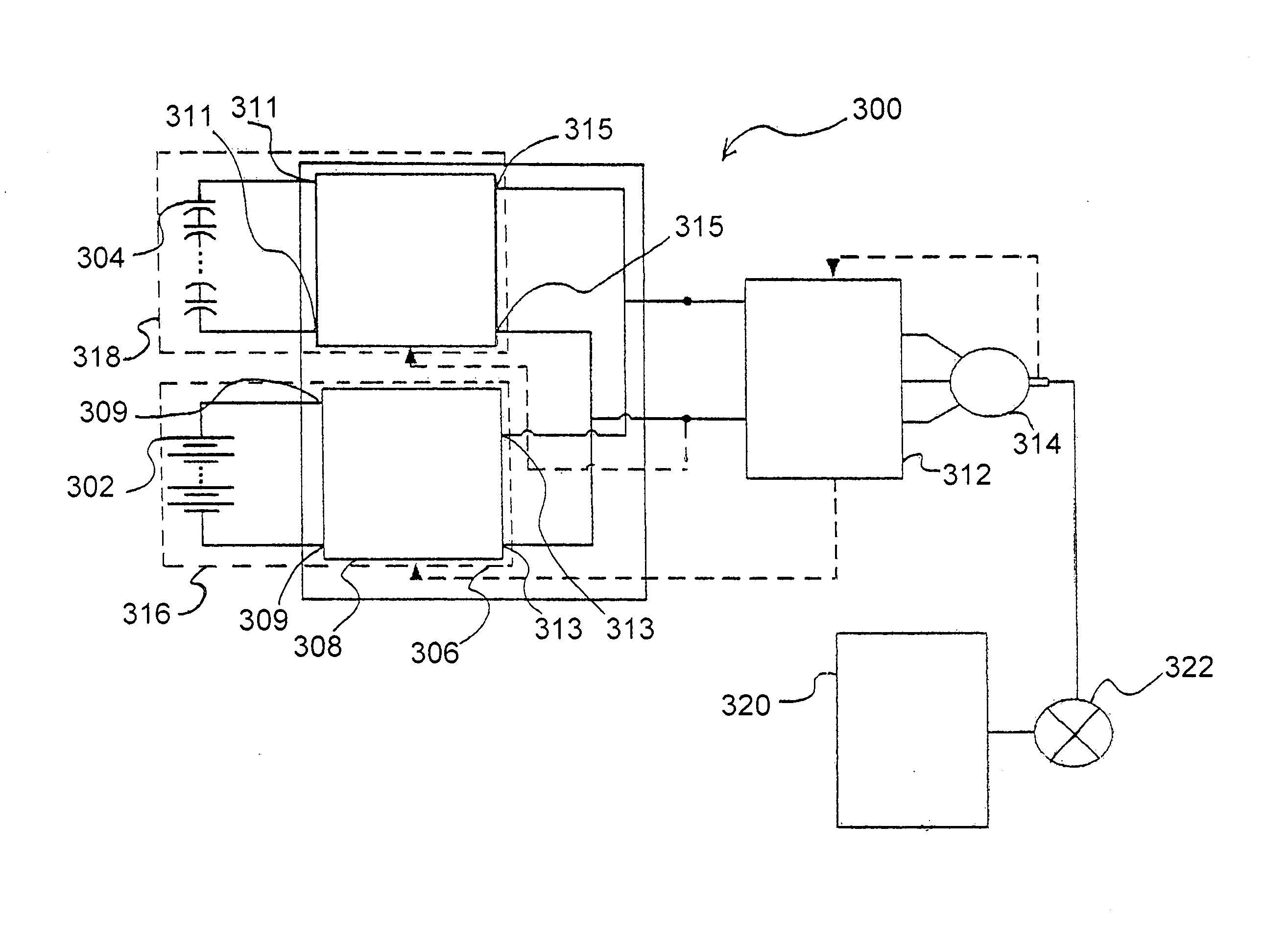
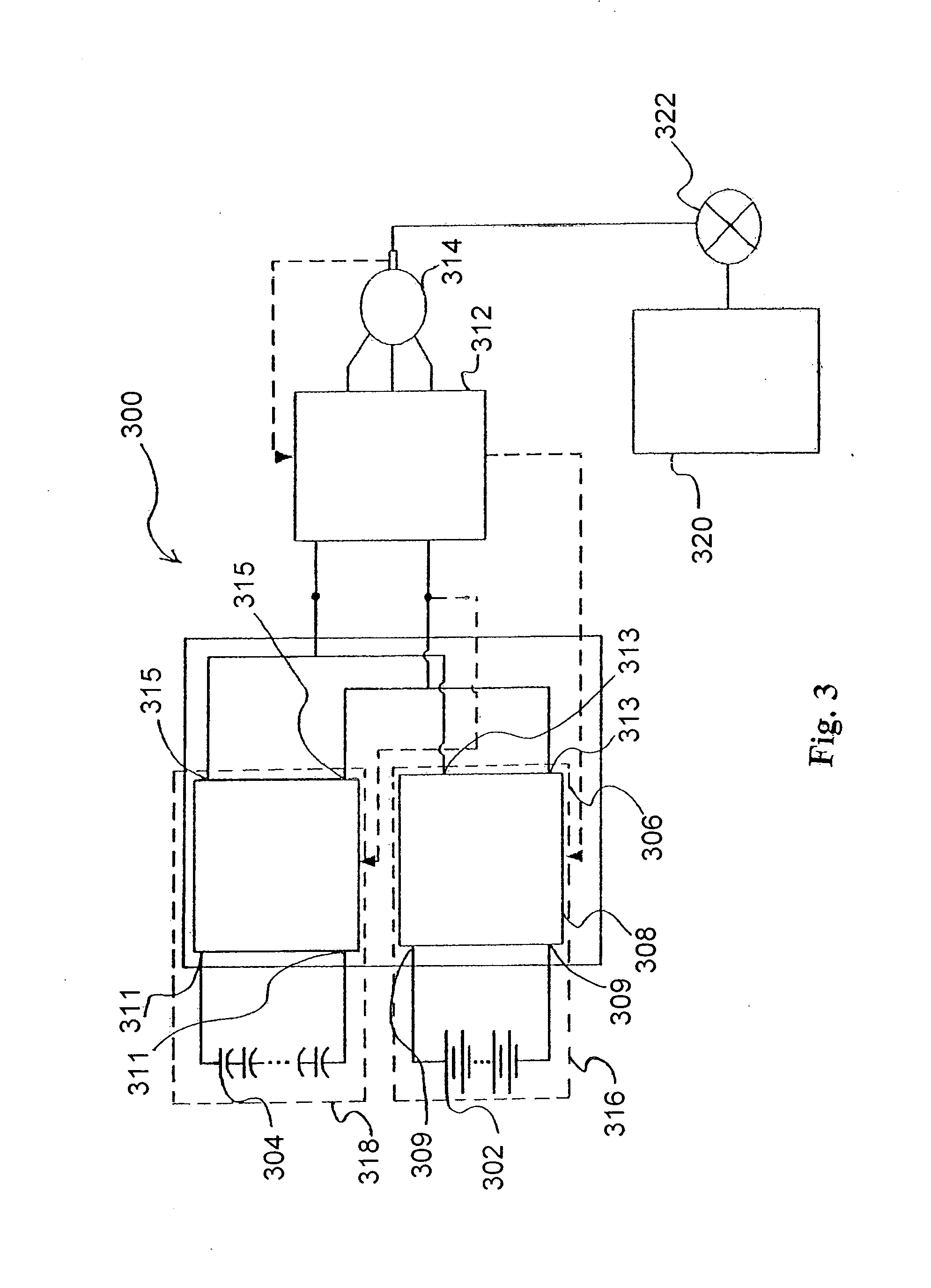
[0027]FIG. 3 illustrates a diagram of a general circuit structure of an electrical energy storage system (EESS) 300 of one embodiment of this invention. The EESS 300 includes a first power source 302, a second power source 304, a two-input bi-directional DC / DC converter 306, a controller 312, an electric motor / generator 314, an internal combustion engine 320, and a drive shaft 322.

[0028]In the embodiment of FIG. 3, the first power source 302 is embodied as a battery or a string of batteries and the second power source 304 is embodied as an ultracapacitor or a string of capacito...


PUM


Abstract

An electric energy storage system (EESS) for providing a power management solution for a multi-subsystem energy storage in electric, hybrid electric, and fuel cell vehicles. The EESS has a controller that determines when to draw power from each subsystem as needed by the vehicle.

Description

CROSS-REFERENCE TO RELATED APPLICATIONS[0001]This application claims the benefit of Provisional U.S. Patent Application Ser. No. 60 / 906,039, filed on 9 Mar. 2007 and Provisional U.S. Patent Application Ser. No. 60 / 967,683, filed on 6 Sep. 2007. The co-pending Provisional Patent Applications are hereby incorporated by reference herein in its entirety and is made a part hereof, including but not limited to those portions which specifically appear hereinafter.BACKGROUND OF THE INVENTION[0002]1. Field of the Invention[0003]The present invention relates generally to power management in vehicles. The present invention relates more specifically to the control of an electric energy storage apparatus for electric, hybrid electric, and fuel cell vehicles.[0004]2. Discussion of the Related Art[0005]In recent years, environmental concerns and foreign oil dependency have increased our nation's interest in a viable alternative to standard internal combustion engines. Some promising alternatives i...

Claims


Application Information

Patent Timeline
IPC IPC(8): H02P1/00B60K1/00B60K6/20H02J1/10H02J7/00
CPCB60L11/005Y02T10/7061H02J7/1423Y02T10/7005Y02T10/7022B60L3/0046B60L11/1803B60L11/1857B60L11/1862B60L11/1866B60L11/1868B60L2210/12B60L2210/14B60L2240/545B60L2240/547B60L2240/549Y02T10/7044Y02T10/7233Y02T10/7225Y02T10/7066B60L11/1864B60L50/40B60L50/51B60L58/16B60L58/13B60L58/21B60L58/22B60L58/20B60L58/18Y02T10/70Y02T10/72
Inventor LUKIC, SRDJANEMADI, ALI
Owner TURNTIDE TECH INC
Why Eureka
Try Eureka