
Arbitrarily-shaped multifunctional structures and method of making

a multifunctional structure and curved surface technology, applied in the direction of waveguide type devices, radiating element structural forms, resonance antennas, etc., can solve the problems of time-consuming and expensive design and manufacture of electronic devices that will be integrated with curved surfaces, and the majority of current electronic antenna systems are precluded from installation on smaller vehicles and protective gear, so as to achieve the effect of increasing performance and functionality

Active Publication Date: 2008-09-11
SI2 TECH
View PDF12 Cites 60 Cited by
  • Summary
  • Abstract
  • Description
  • Claims
  • Application Information

AI Technical Summary

Benefits of technology

[0013]More innovative methods of incorporating electronic functions into vehicles, protective and military equipment are needed to make the aforementioned structures more efficient in meeting varied functional requirements simultaneously. Accordingly, ther

Problems solved by technology

Most current electronic antenna systems, however, are suboptimal and are often precluded from installation on smaller vehicles and protective gear due to the large size and weight of the required antennas.
Thus, the design and manufacture of electronic devices that will be integrated with curved surfaces is both time consuming and expensive.
For example, the electronic devices must be fabricated on substrates with known and consistent dielectric properties so thai they function as expected and desired, in addition, conventional electronic fabrication techniques involve vacuum deposition, plating, etching and lamination which require the substrate material to be able to withstand high temperatures and / or chemical solutions; environments which may not be suitable for structural materials.
Hence, the number of high performance electronic substrates currently available for use in multifunctional structures is limited.
Hence, these load-bearing antenna structures are not completely optimized, as the structural materials frequently do not have the required electronic properties, and the electronics are not fully integrated with the structure.
Further, conventional electronic substrates typically do not exhibit the required mechanical properties such that they could tolerate significant in-service mechanical loads.
Conventional electronics manufacturing processes are limited in their ability to manufacture shape-conformal electronics.
Thus, the prior art approaches are able to fabricate structures and electronics using techniques and substrate materials which are industry limited.
Because the electronics are formed on a substrate which is not load-bearing, the embedded electronics will represent a mechanical defect for the wing.
The design of the aircraft wing and of the electronics may be easier using this conventional approach, but the performance of each component is compromised when the two are integrated (meshed together).

Method used


Image

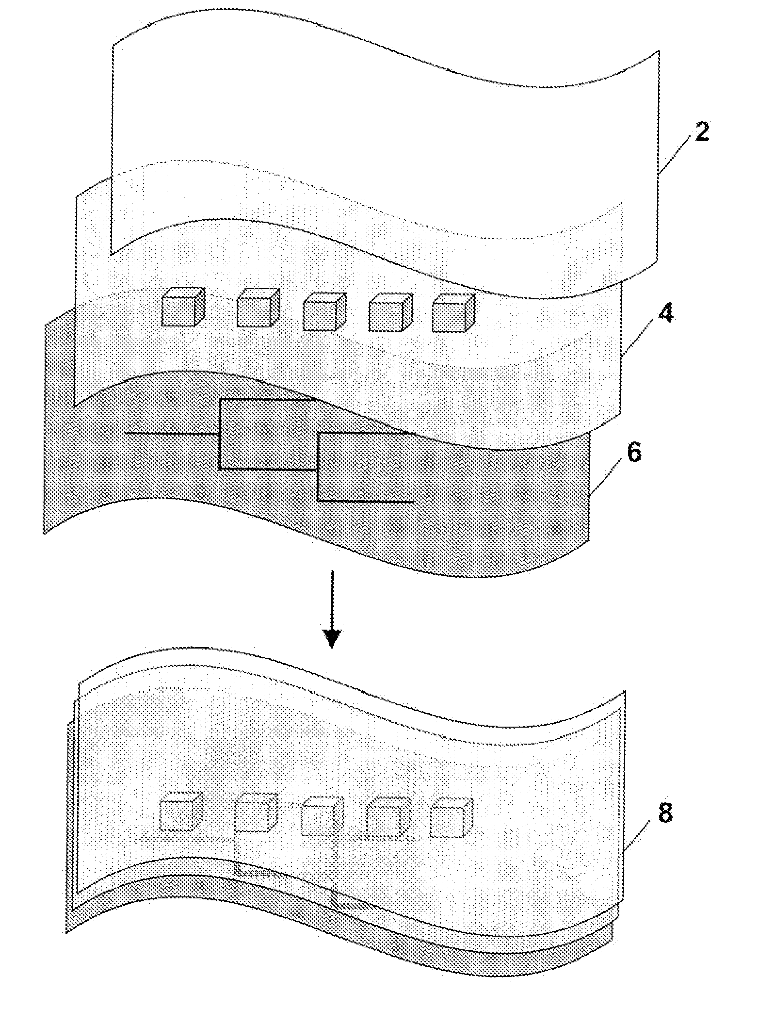
  • Arbitrarily-shaped multifunctional structures and method of making
  • Arbitrarily-shaped multifunctional structures and method of making
  • Arbitrarily-shaped multifunctional structures and method of making

Examples


Embodiment Construction

[0036]Before the present devices, systems and methods are described, it is to be understood that this invention is not limited to the particular processes, devices, or methodologies described, as these may vary. It is also to be understood that the terminology used in the description is for the purpose of describing the particular versions or embodiments only, and is not intended to limit the scope of the present disclosure which will be limited only by the appended claims.

[0037]It must also be noted that as used herein and in the appended claims, the singular forms “a”, “an”, and “the” include plural reference unless the context clearly dictates otherwise. Thus, for example, reference to a “device” is a reference to one or more devices and equivalents thereof known to those skilled in the art, and so forth. “Optional” or “optionally” means that the subsequently described structure, event or circumstance may or may not occur, and that the description includes instances where the str...


PUM

PropertyMeasurementUnit
Temperatureaaaaaaaaaa
Electrical conductivityaaaaaaaaaa
Densityaaaaaaaaaa

Abstract

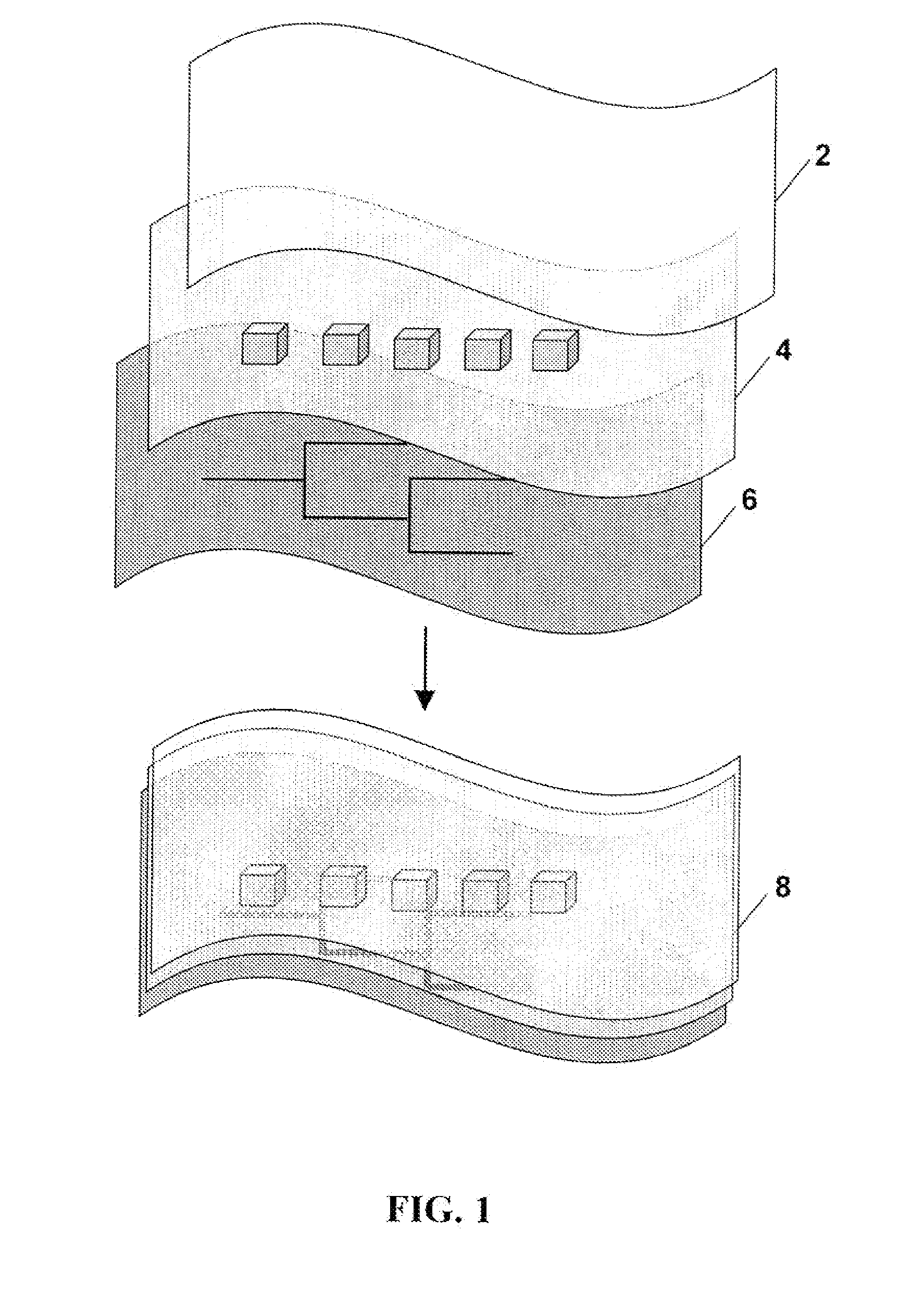
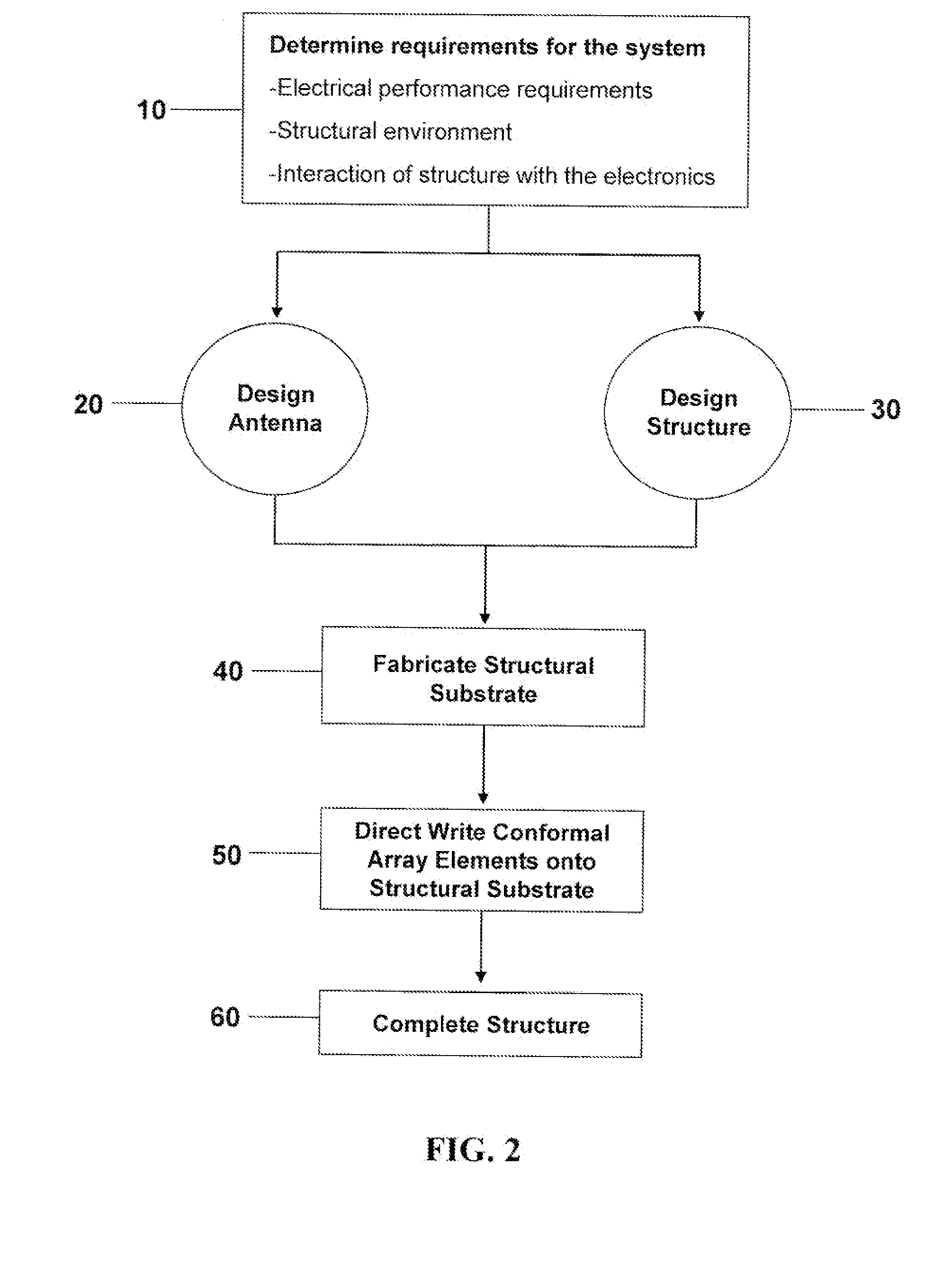
Multifunctional structures and methods of manufacturing multifunctional structures which function as both electronic devices and load-bearing elements are disclosed. The load-bearing elements are designed to have electronic functionality using electronics designed to be load-bearing. The method of manufacturing the multifunctional structure comprises forming an electronic element directly on at least one ply of arbitrarily shaped load-bearing material using conventional lithographic techniques and / or direct write fabrication techniques, and assembling at least two plies of arbitrarily shaped load-bearing material into a multifunctional structure. The multifunctional structure may be part of an aerospace structure, part of a land vehicle, pan of a watercraft or part of a spacecraft.

Description

CROSS-REFERENCE TO RELATED APPLICATIONS[0001]This application claims priority to U.S. Provisional Application No. 60 / 887,692 filed Feb. 1, 2007 titled “Arbitrarily-Shaped Multifunctional Structures and Method of Making”, which application is incorporated herein by reference.STATEMENT REGARDING FEDERALLY SPONSORED RESEARCH[0002]This invention was made with United States Government support under contract F33615-03-M-3345 awarded by the U.S. Air Force. The U.S. Government may have certain interests to this application.THE NAMES OF THE PARTIES TO A JOINT RESEARCH AGREEMENT[0003]Not ApplicableINCORPORATION-BY-REFERENCE OF MATERIAL ON DISC[0004]Not ApplicableBACKGROUND[0005]1. Technical Field[0006]The disclosure contained herein generally relates to multifunctional structures and methods of manufacturing multi-ply, multifunctional structures. In particular, the multifunctional structures of the disclosure function as both electronic devices and load-bearing elements.[0007]2. Description o...

Claims


Application Information

Patent Timeline
IPC IPC(8): H01Q9/04H01P11/00H01Q1/28H01Q1/34H01Q1/32
CPCH01Q21/065Y10T29/49016H01Q1/27H01Q1/28
Inventor HANDY, ERIK S.KUNZE, JOSEPH M.
Owner SI2 TECH
Learn More