
Quantum cascade laser device

Inactive Publication Date: 2008-09-11
HAMAMATSU PHOTONICS KK
View PDF3 Cites 18 Cited by
  • Summary
  • Abstract
  • Description
  • Claims
  • Application Information

AI Technical Summary

Benefits of technology

[0009]The present invention has been made in order to solve the above-described problem, and it is an object of the present invention to provide a quantum cascade laser device which has high slope efficiency, and is capable of stably realizing a single transverse mode operation.
[0011]In this way, because a cross-sectional shape of the laminate structure is a rectangle or an inverted mesa shape, the quantum cascade laser device according to the present invention has high slope efficiency, and is capable of stably realizing a single transverse mode operation. Further, because heat generated in the active layer during driving is radiated through the insulating layers, the radiation performance is improved.
[0012]The quantum cascade laser device according to the present invention has high slope efficiency, and is capable of stably achieving a single transverse mode operation.

Problems solved by technology

In accordance therewith, this device is not efficient in its current confinement, and which leads to low slope efficiency (a ratio (ΔP / ΔI) of a light output increment ΔP with respect to a current increment ΔI during laser oscillation).
Further, because a width of a light emitting layer is broadened, it is difficult to achieve single transverse mode operation.

Method used


Image

  • Quantum cascade laser device
  • Quantum cascade laser device
  • Quantum cascade laser device

Examples


first embodiment

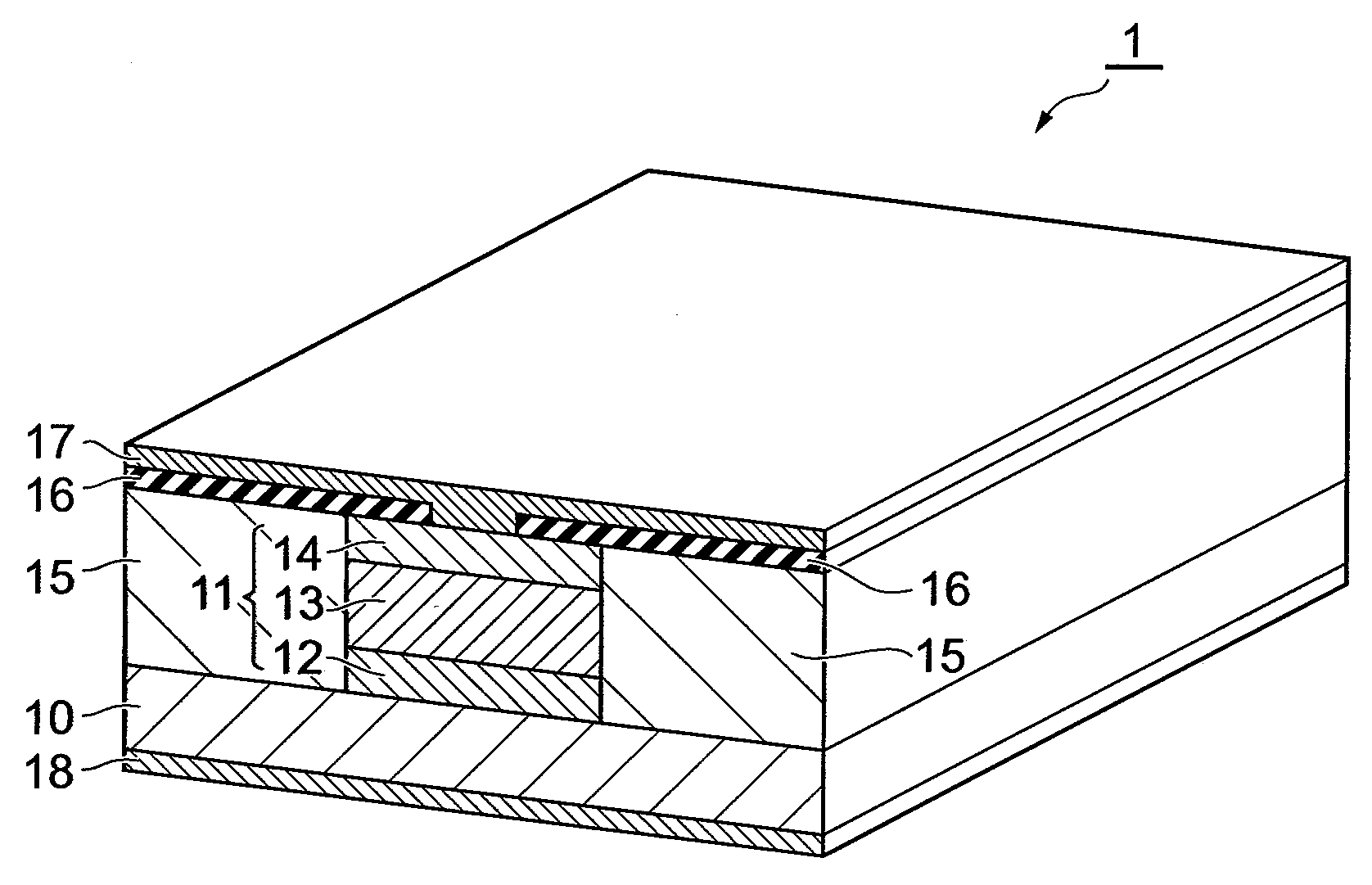
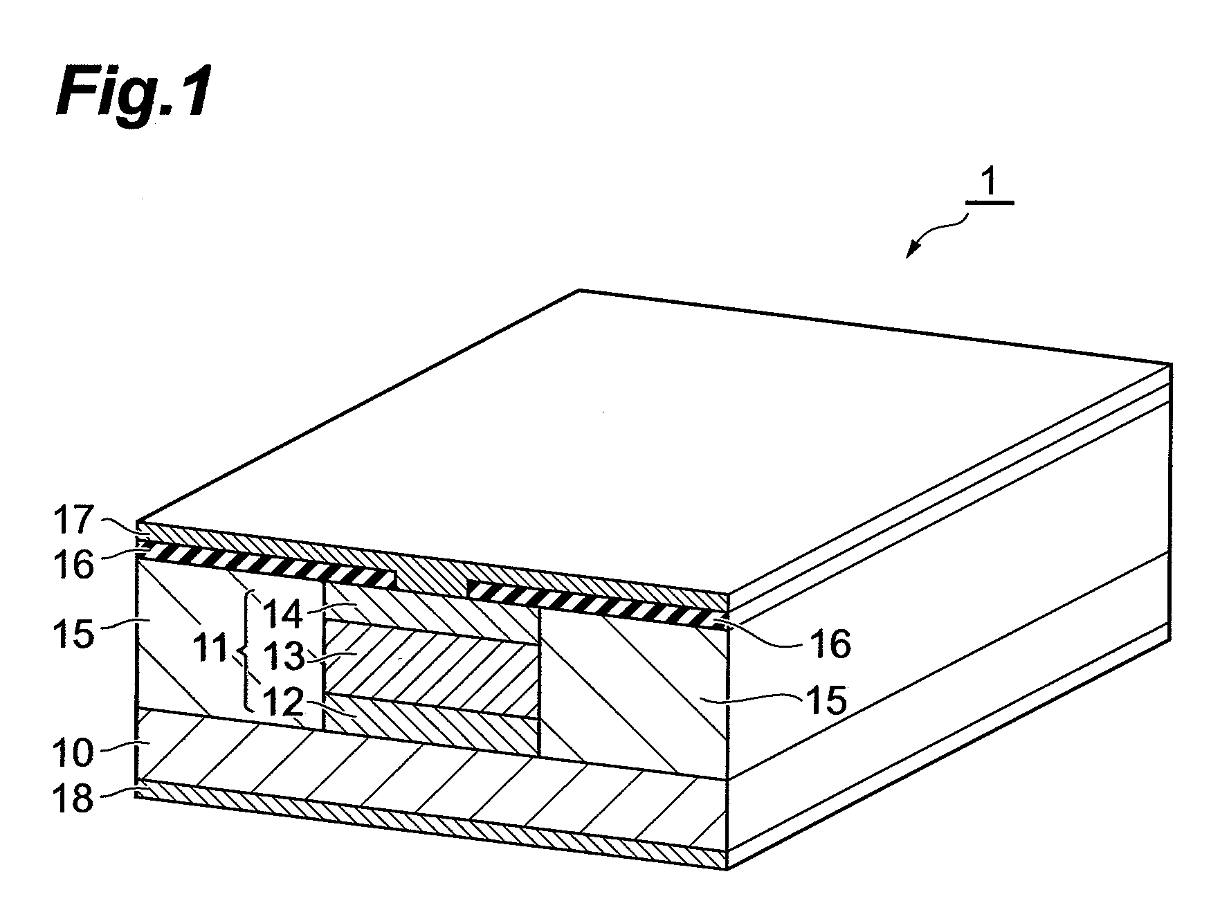
[0024]First, a first embodiment of a quantum cascade laser device according to the present invention will be described. FIG. 1 is a perspective view of a quantum cascade laser device 1 according to the first embodiment. In the quantum cascade laser device 1 shown in this figure, a laminate structure 11 is formed in a stripe shape along a predetermined direction on a principal surface at one side of a substrate 10, and insulating layers 15 are formed on the bilateral sides of the laminate structure 11, and an insulating layer 16 and a metal layer 17 are formed in sequence on the laminate structure 11 and the insulating layers 15. Further, a metal layer 18 is formed on a principal surface at the other side of the substrate 10. The both end faces of the laminate structure 11 serve as mirrors of a laser resonator.

[0025]The laminate structure 11 is formed such that a cladding layer 12, an active layer 13, and a cladding layer 14 are formed in sequence from the side of the substrate 10. I...

second embodiment

[0041]Next, a second embodiment of the quantum cascade laser device according to the present invention will be described. FIG. 6 is a perspective view of a quantum cascade laser device 2 according to the second embodiment. In the quantum cascade laser device 2 shown in this figure, the laminate structure 11 is formed in a stripe shape along a predetermined direction on a principal surface at one side of the substrate 10, and the insulating layers 15 are formed on the bilateral sides of the laminate structure 11, and the insulating layer 16 and the metal layer 17 are formed in sequence on the laminate structure 11 and the insulating layers 15. Further, the metal layer 18 is formed on a principal surface at the other side of the substrate 10. The both end faces of the laminate structure 11 serve as mirrors configuring a laser resonator.

[0042]The laminate structure 11 is formed such that the cladding layer 12, the active layer 13, and the cladding layer 14 are formed in sequence from t...


PUM


Abstract

In a quantum cascade laser device 1, a laminate structure 11 is formed into a stripe shape along a predetermined direction on a principal surface at one side of a substrate 10, and insulating layers 15 are formed on bilateral sides of the laminate structure 11, and an insulating layer 16 and a metal layer 17 are formed in sequence on the laminate structure 11 and the insulating layers 15. The laminate structure 11 is formed such that a cladding layer 12, an active layer 13, and a cladding layer 14 are formed in sequence from the side of the substrate 10. In the active layer 13, light emitting layers and injection layers are alternately laminated, and the active layer 13 generates light due to intersubband electron transition in a quantum well structure. A shape in a cross section of the laminate structure 11 perpendicular to the direction in which the laminate structure 11 is provided to extend is formed into a rectangle or an inverted mesa shape. In accordance therewith, it is possible to realize a quantum cascade laser device having high slope efficiency, and being capable of stably realizing a single transverse mode operation.

Description

BACKGROUND OF THE INVENTION[0001]1. Field of the Invention[0002]The present invention relates to a quantum cascade laser device.[0003]2. Related Background Art[0004]A quantum cascade laser device is a monopolar type element, in which a laminate structure including an active layer in which light emitting layers and injection layers are alternately laminated is formed on a principal surface of a substrate, and which is capable of generating light due to intersubband electron transition in a quantum well structure in the active layer. A quantum cascade laser device is capable of realizing high-efficiency and high-power operation due to an active layer in which light emitting layers and injection layers are alternately disposed in a multistage configuration and in a cascade manner, and is expected as a high-performance semiconductor light source in a region from mid-infrared to THz wavelengths.[0005]In a quantum cascade laser device, when a voltage is applied between the upper and lower...

Claims


Application Information

Patent Timeline
IPC IPC(8): H01S5/30
CPCB82Y20/00H01S5/2214H01S5/2226H01S2301/18H01S5/2275H01S5/3402H01S5/227
Inventor SUGIYAMA, ATSUSHIOCHIAI, TAKAHIDEFUJITA, KAZUUEAKIKUSA, NAOTAEDAMURA, TADATAKAFURUTA, SHINICHI
Owner HAMAMATSU PHOTONICS KK
Learn More