Delivery of Low Pressure Dopant Gas to a High Voltage Ion Source

a high-voltage ion source and low-pressure dopant technology, which is applied in the direction of ion beam tubes, instruments, nuclear engineering, etc., can solve the problems of inability to deliver toxic, corrosive or flammable dopants to the ion source unit, no acceptable way, and risk of arcing and plasma discharge in the gas lin

Inactive Publication Date: 2008-09-11
ENTEGRIS INC
View PDF6 Cites 24 Cited by
  • Summary
  • Abstract
  • Description
  • Claims
  • Application Information

AI Technical Summary

Benefits of technology

[0021]A still further aspect of the invention relates to a method of manufacturing a semiconductor product, including ion implantation using a low-pressure gas, ionizing the low-pressure gas to produce ion implant species, and impinging the ion implant species on a semiconductor device substrate to produce an implanted substrate article, in which the method includes flowing the low-pressure gas through a gas flow path to an ion source for such ionizing, imposing an electrical field on a least a portion of the gas flow path, and modulating acceleration length of electrons of the low-pressure gas i...

Problems solved by technology

The foregoing ion implantation system, while generally effective, suffers the deficiency that it has not been possible to deliver toxic, corrosive or flammable dopants to the ion source unit from dopant gas supply vessels at ground potential.
There are two primary reasons for such deficiency:(1) The gas delivery line from the dopant gas supply vessel would have to be made of insulating material, and for high pressure dopant supplies there is no acceptable way to deliver the high-pressure gas due to safety issues related to the reliability of insulating lines and connections to such lines, as required to accommodate high pressure dopant gas delivery operation.(2) For low-pressure (e.g., sub-atmospheric pressure) dopant gas supplies, such as the aforementioned SDS® dopant gas supply, there is a risk of ar...

Method used


Image

  • Delivery of Low Pressure Dopant Gas to a High Voltage Ion Source
  • Delivery of Low Pressure Dopant Gas to a High Voltage Ion Source
  • Delivery of Low Pressure Dopant Gas to a High Voltage Ion Source

Examples


Embodiment Construction

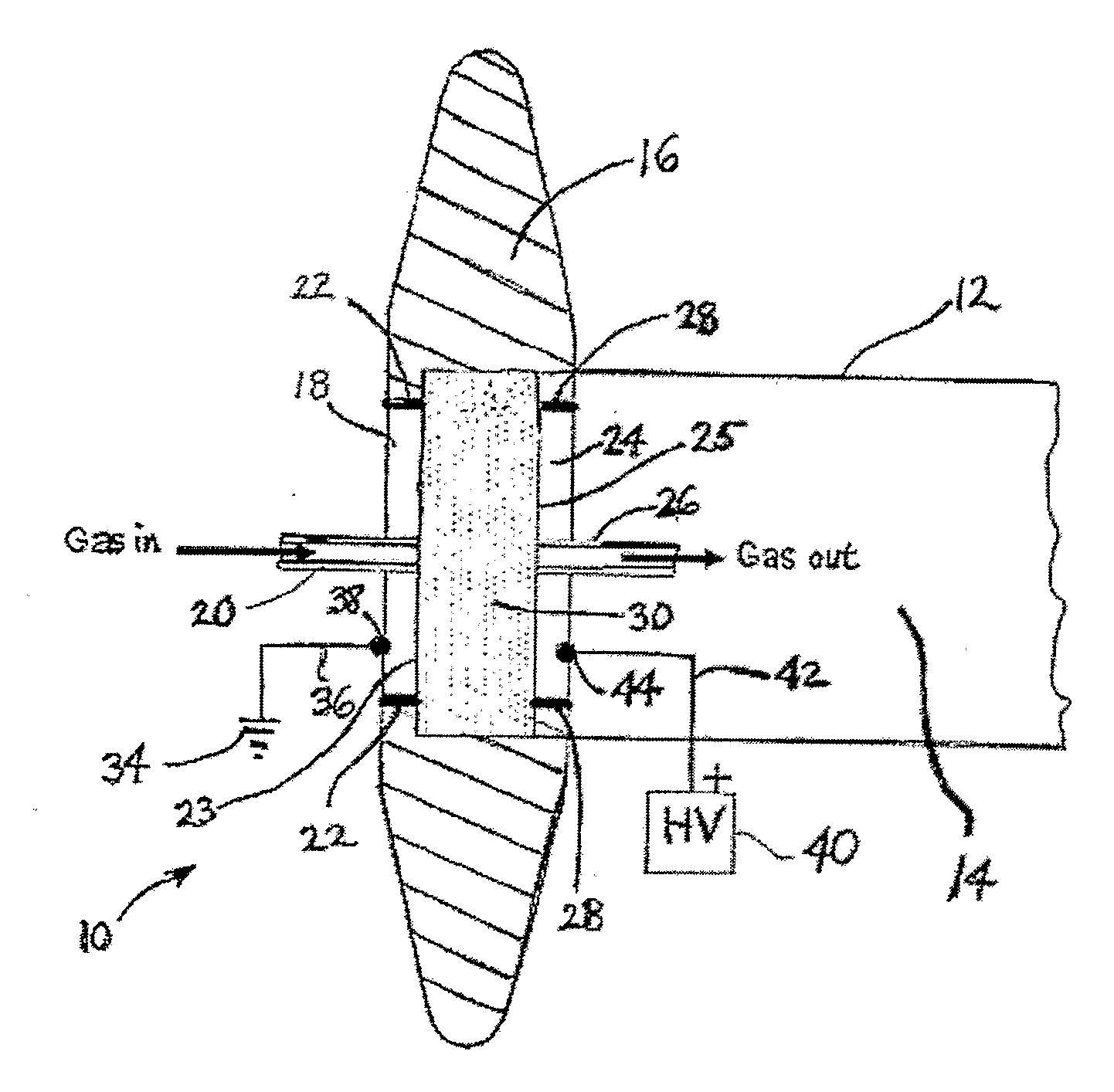
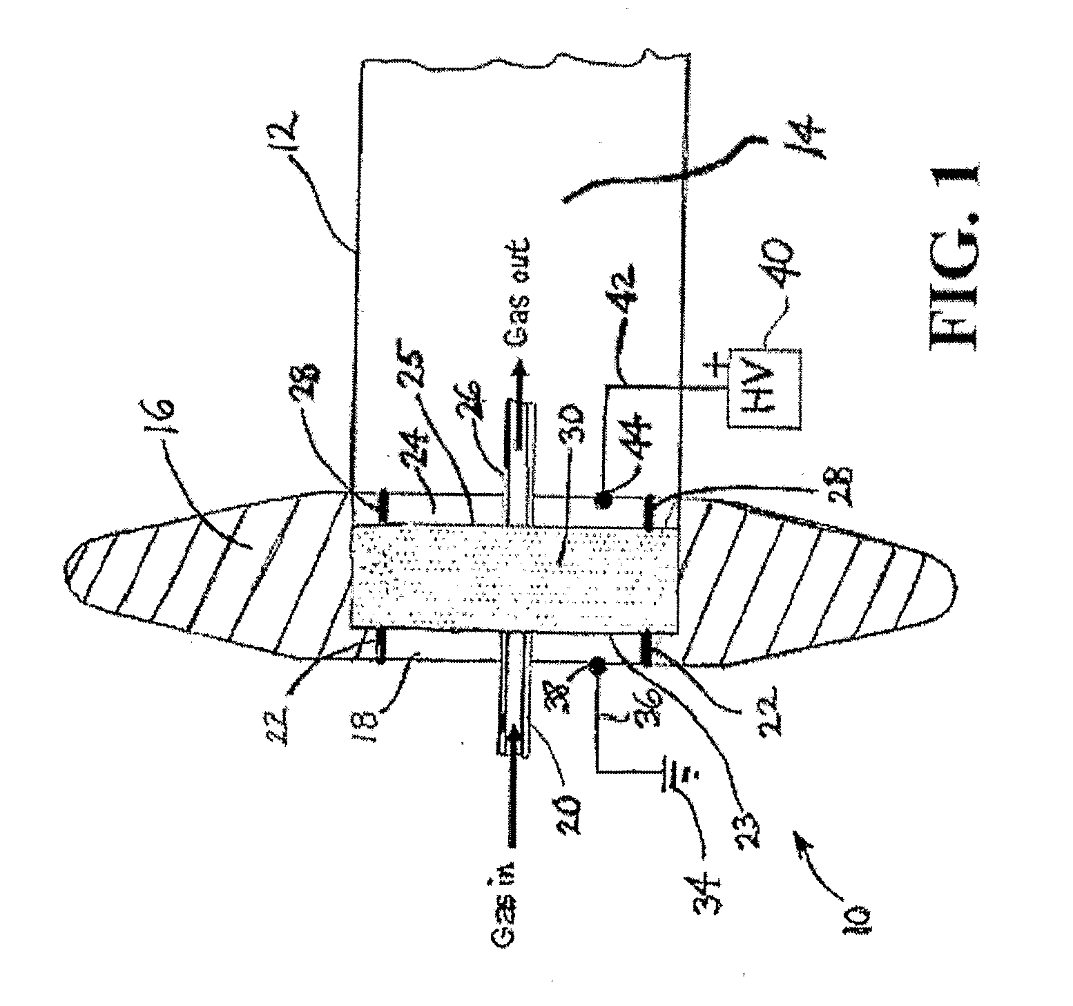
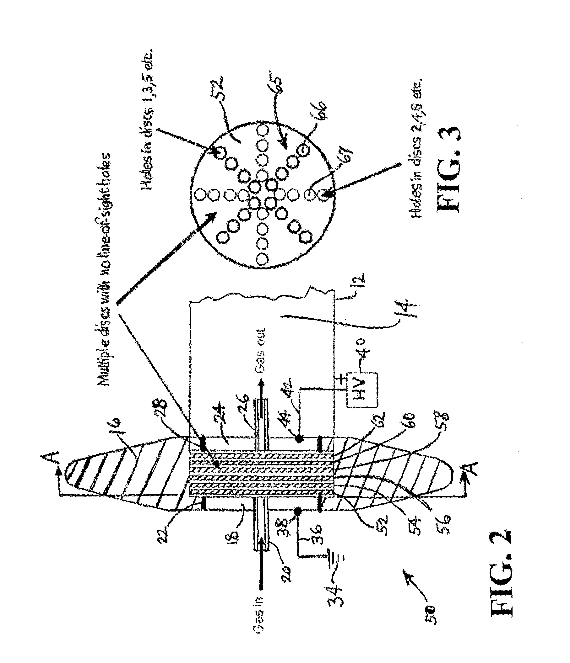
[0031]The present invention relates to delivery of low-pressure dopant gas to a high voltage ion source in the doping of materials such as semiconductor substrates.

[0032]The disclosures of U.S. Pat. No. 5,518,528 issued May 21, 1996 to Glenn M. Tom, et al. and U.S. Pat. No. 6,515,290 issued Feb. 4, 2003 Rzeszut, et al. are hereby incorporated herein by reference, in their respective entireties.

[0033]The present invention enables delivery of toxic, corrosive or flammable dopant gases from cylinders at ground potential to an ion source at high voltage. The gases must be delivered (i) safely, i.e. with no risk of catastrophic release and (ii) without risk of ionization of the gas by the electric field, which could short the high voltage.

[0034]The present invention prevents ionization discharges in low-pressure gas flowing in electric fields of the magnitude existing in external insulators in an ion implanter, viz., ˜4 kV / cm.

[0035]As used herein, the term “low-pressure” in reference to ...


PUM


Abstract

A system for delivery of low-pressure dopant gas to a high-voltage ion source in the doping of semiconductor substrates, in which undesired ionization of the gas is suppressed prior to entry into the high-voltage ion source, by modulating electron energy upstream of the high-voltage ion source so that electron acceleration effects are reduced to below a level supporting an electronic ionization cascade. The gas delivery system in a specific application includes a gas flow passage, a voltage generator electrically coupled with at least a portion of the gas flow passage to impose an electric field thereon, and an obstructive structure that is deployed to modulate acceleration length of electrons of the low-pressure gas in relation to ionization potential of the gas, to suppress ionization in the gas flow passage.

Description

BACKGROUND OF THE INVENTION[0001]1. Field of the Invention[0002]The present invention relates to delivery of low-pressure dopant gas to a high voltage ion source in the doping of materials such as semiconductor substrates.[0003]2. Description of the Related Art[0004]U.S. Pat. No. 5,518,528 issued May 21, 1996 to Glenn M. Tom, et al. describes an adsorbent-based fluid storage and delivery system useful in the supply of gas for semiconductor manufacturing operations, e.g., ion implantation. In such system, fluid is sorptively retained on a physical adsorbent medium of suitable adsorptive affinity in a fluid storage and dispensing vessel, and the fluid is desorbed from the physical adsorbent medium under dispensing conditions. The fluid storage and dispensing vessel can for example be a metal cylinder, and the dispensing conditions can involve a thermally-assisted desorption of the fluid from the adsorbent medium, pressure-differential-based desorption of the fluid from the adsorbent m...

Claims


Application Information

Patent Timeline
IPC IPC(8): H01L21/265H01J37/317H01J37/08
CPCH01J27/02H01J2237/0203H01J37/3172H01J37/08H01L21/22
Inventor OLANDER, W. KARLARNO, JOSE I.KAIM, ROBERT
Owner ENTEGRIS INC
Why Eureka
Try Eureka