Medical implant with reinforcement mechanism

a technology of reinforcement mechanism and medical implants, applied in the field of medical implants, to achieve the effect of improving the efficacy and controllability of the implant during use, reducing or eliminating undesirable stresses and strains, and enhancing the structural integrity of the implan

Inactive Publication Date: 2008-09-11
EDWARDS LIFESCIENCES CORP
View PDF97 Cites 21 Cited by
  • Summary
  • Abstract
  • Description
  • Claims
  • Application Information

AI Technical Summary

Benefits of technology

[0006]Embodiments of the present invention provide an improved device and method for treating mitral regurgitation in a minimally-invasive manner. Certain embodiments provide an improved implant which is configured for deployment partially or entirely within a coronary sinus. The improved implant is preferably formed with a composite structure wherein a reinforcement mechanism is combined with a metallic member. The reinforcement mechanism enhances the structural integrity of the implant by reducing or eliminating undesirable stresses and strains in the metallic member. The reinforcement mechanism also improves the efficacy and controllability of the implant during use. The implant is preferably configured to provide a low profile after deployment in the coronary sinus. The implant is also preferably configured to accelerate tissue ingrowth for enhanced anchoring after deployment.

Problems solved by technology

Furthermore, the reinforcement mechanism provides a redundant attachment mechanism which prevents complete separation in the event of a structural failure.

Method used


Image

  • Medical implant with reinforcement mechanism
  • Medical implant with reinforcement mechanism
  • Medical implant with reinforcement mechanism

Examples


Embodiment Construction

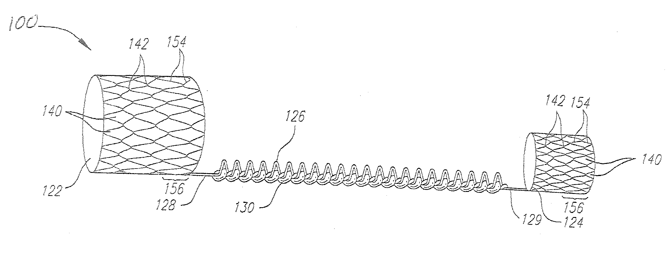
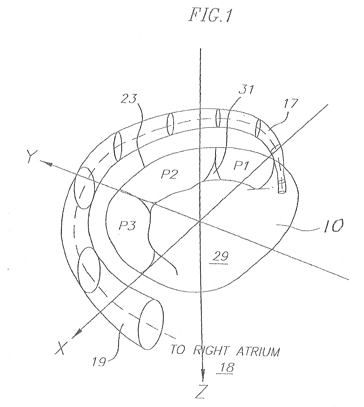
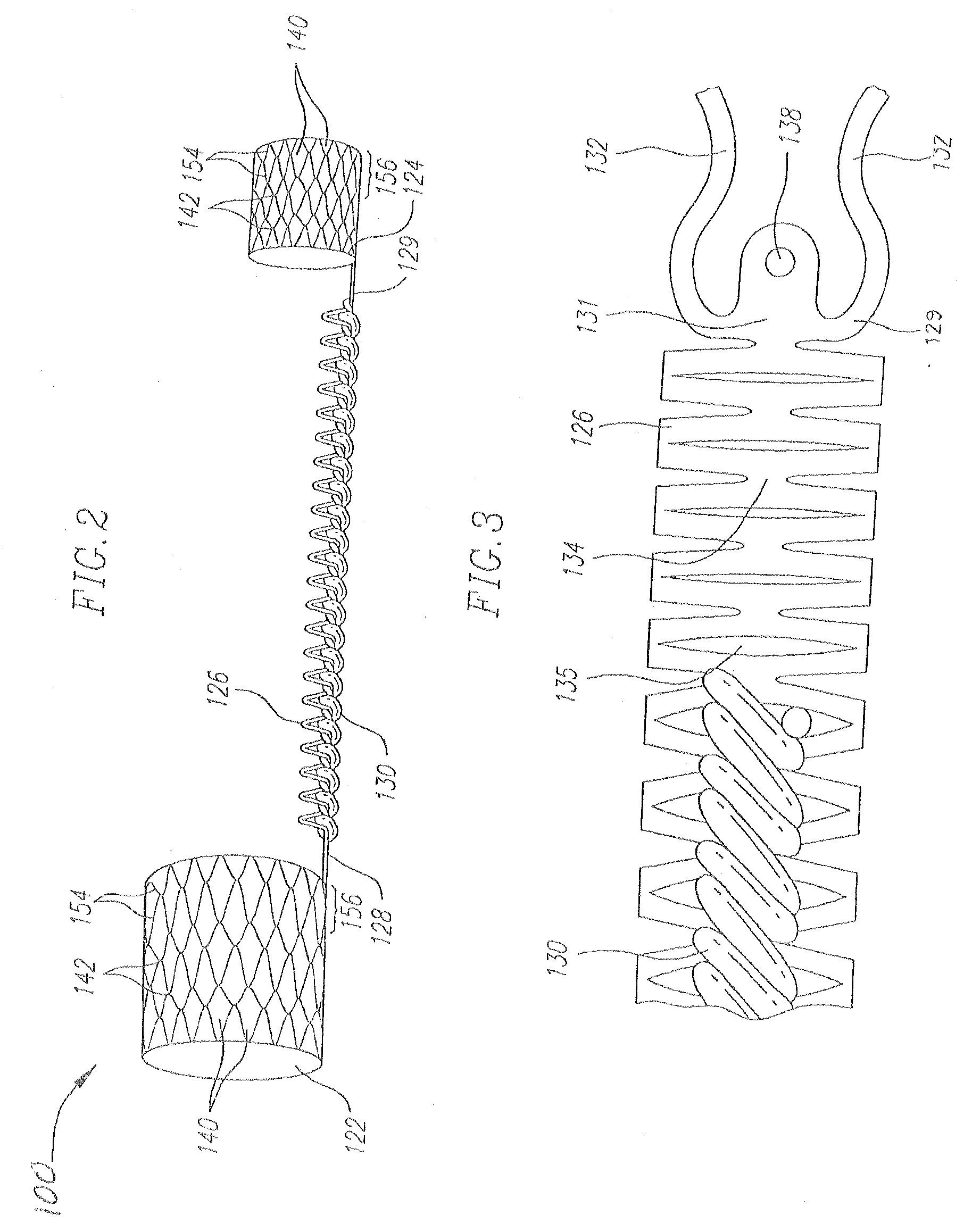
[0032]Various embodiments of the present invention depict medical devices and methods of use that are well-suited for treating mitral valve regurgitation. However, it should be appreciated that the principles and aspects of the embodiments disclosed and discussed herein are also applicable to other devices having different structures and functionalities. For example, certain structures and methods disclosed herein may also be applicable to other medical devices. In particular, certain structures and methods disclosed herein may be applicable to various other types of medical devices made from shape memory materials. Furthermore, certain embodiments may also be used in conjunction with other medical devices or other procedures not explicitly disclosed. The manner of adapting the embodiments described herein to various other devices and functionalities will become apparent to those of skill in the art in view of the description that follows.

[0033]As used herein, “distal” means the dir...


PUM


Abstract

An improved medical implant for treating mitral regurgitation is provided. The medical implant comprises proximal and distal anchors connected by a bridge. The medical implant is configured to be delivered into a coronary sinus using a minimially invasive procedure. The bridge is preferably made of a shape memory material which is biased to contract after the implant is delivered. The medical implant further comprises a reinforcement mechanism configured to limit stresses and strains along the length of the bridge. In a preferred embodiment, the reinforcement mechanism is fixed to a plurality of attachment points along the bridge, thereby preventing excessive elongation between any two attachment points. A resorbable material is preferably disposed within gaps along the length of the bridge to temporarily maintain the bridge in an elongated condition. After the proximal and distal anchors are secured in the coronary sinus, the resorbable material gradually resorbs, thereby creating tension in the bridge which applies a force along the mitral valve annulus. The reinforcement mechanism ensures that stresses and strains and distributed evenly while the bridge is in tension.

Description

RELATED APPLICATIONS[0001]The present application is a continuation-in-part of application Ser. No. 11 / 502,879, filed on Aug. 11, 2006, entitled “Medical Implant with Reinforcement Mechanism,” which claims priority under 35 U.S.C. §119(e) to U.S. Provisional Application No. 60 / 707,926, filed on Aug. 12, 2005, the entirety of each of which is incorporated by reference.FIELD OF THE INVENTION[0002]The present invention relates to medical implants, and more particularly to medical implants configured for treating mitral valve regurgitation.BACKGROUND[0003]The mitral valve is located between the left atrium and left ventricle of the heart. Mitral regurgitation, or leakage from the outflow to the inflow side of the mitral valve, is the most common type of heart valve insufficiency. Mitral regurgitation becomes chronic when the condition persists rather than occurring for only a short time period. Any disorder that weakens or damages the mitral valve may prevent it from closing properly, c...

Claims


Application Information

Patent Timeline
Patent Type & Authority Applications(United States)
IPC IPC(8): A61F2/24
CPCA61F2/2451
Inventor BOBO, DONALDBAKIS, GEORGEMA, MINH T.CORSO, PHILIP P.
Owner EDWARDS LIFESCIENCES CORP
Why Eureka
Try Eureka