
Hemi-implant for first metatarsophalangeal joint

a technology of metatarsophalangeal joints and implants, which is applied in the field of partial joint replacement implants and first metatarsophalangeal joints, can solve the problems of human body damage, full joint replacement using silicone materials, and concern for its potential damage to the body, and achieves simple but effective retention structures and extended length to the stem

Inactive Publication Date: 2008-09-11
LOWE JOHN PATRICK TRUSTEE CHAPTER 7 CASE NO 09 51026 C IN THE UNITED STATES BANKRUPTCY COURT FOR THE WESTERN DISTRICT OF TEXAS SAN ANTONIO DIV
View PDF19 Cites 78 Cited by
  • Summary
  • Abstract
  • Description
  • Claims
  • Application Information

AI Technical Summary

Benefits of technology

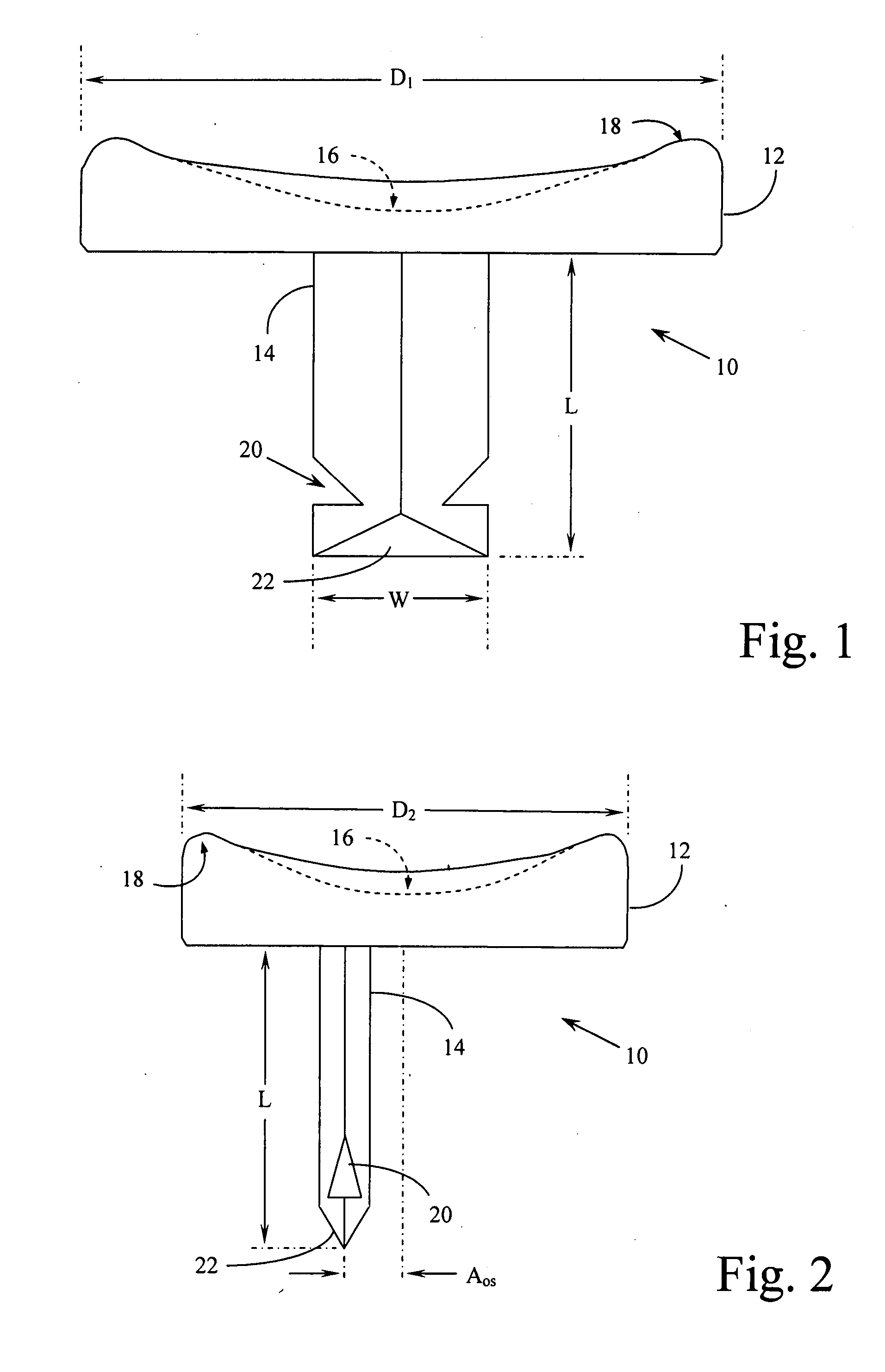
[0014]Structures, geometries, and methods of use associated with the present invention allow the physician to more securely place the implant with less risk of bone damage and further to provide greater comfort to the patient as a result of more accurate placement and more appropriate sizing of the implant. Further benefits of the structural and functional design of the hemi-implant of the present invention will become apparent to those skilled in the art upon an understanding of the detailed description of the preferred embodiments which refers specifically to the drawing figures attached, a brief description of which follows immediately below.

Problems solved by technology

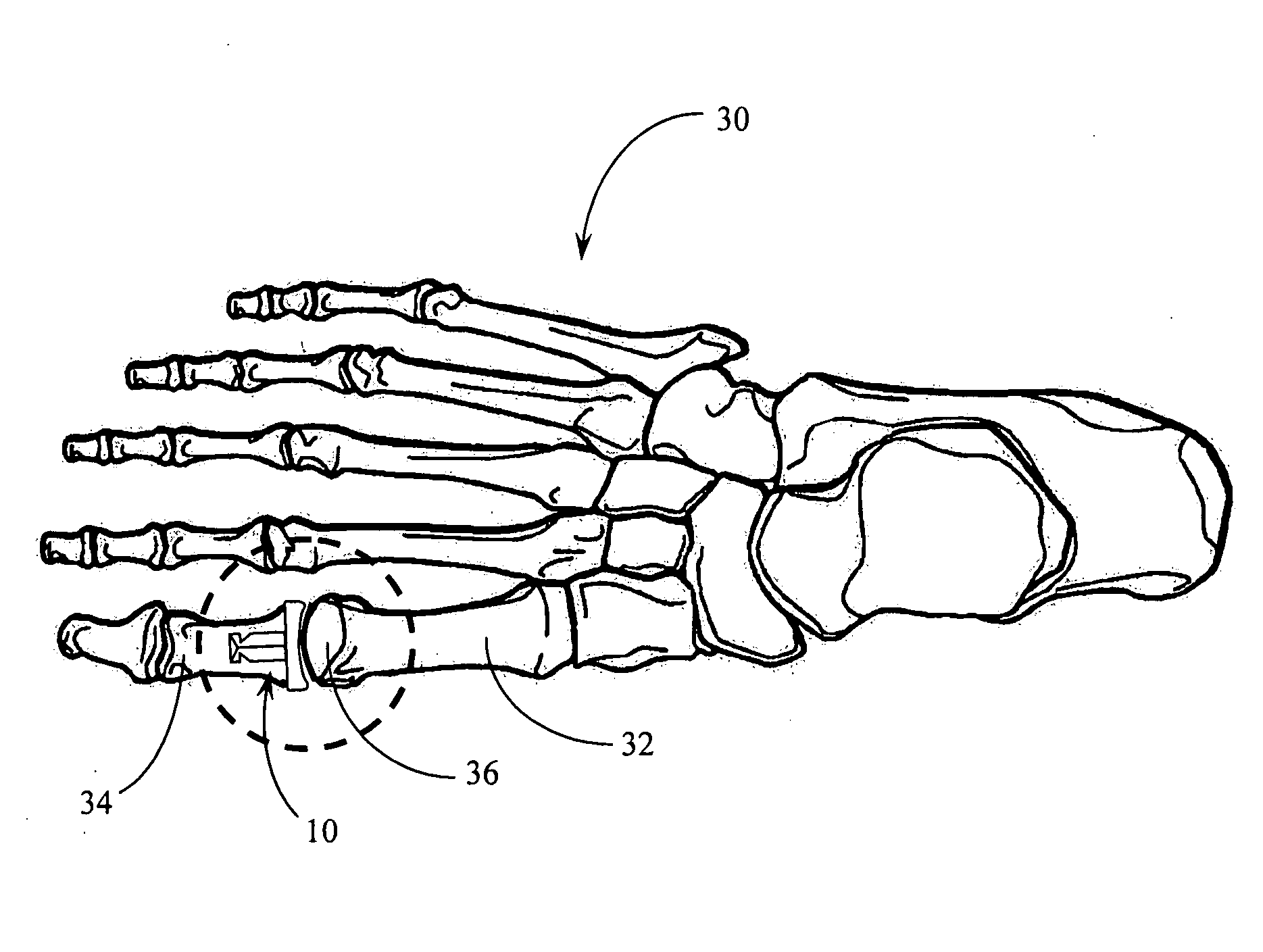
Among the many joints associated with the bones of the human foot, one that is known to cause frequent problems is the metatarsophalangeal joint between the first metatarsal and the first phalanx in what is commonly known as the hallux or great toe.
Silicone material, however, has generally been found to be too soft for the purpose of maintaining an appropriate joint surface and will eventually break down into particles that can have damaging effects on the human body.
Despite the absence of an abrasive motion of the silicone material against a bone surface in the joint, degradation of the silicone material formed into this hinge type joint replacement continues to cause concern for its potential damaging effects on the body.
Such full joint replacement using silicone material, therefore, is also not a preferred solution even where both surfaces of the joint require replacement.
In general, it is preferred not to replace both sides of the joint with metal implants, as this will frequently result in joint discomfort and / or progressive dislocation of the joint often resulting in joint stiffness.
Many such efforts have created circular or conical stems that, while presenting increased surface area for contact, frequently suffer from rotation after placement.
Other efforts at creating suitable stem configurations for the implant have focused on a variety of non-rotating configurations, often at the cost of decreased surface contact.
Unfortunately, the adequate use of such rectangular wedge shaped stem designs depends greatly on the condition of the phalanx bone and the ability of the physician to provide a receptor opening in the bone that is neither too large nor too small.
Excavating or broaching too much of the bone, of course, provides a loose placement of the implant, while failing to excavate or broach enough of the bone can result in fractures during placement.
Such centered placement, however, fails to recognize that the largest, most stable portion of the phalanx bone available for use as a means for retaining the implant does not lie immediately distal to the center axis of the joint.
Placing the stem of the implant device along the center line of the joint significantly limits the quantity (and often quality) of bone surrounding the stem and further limits how wide the stem can be and how long the stem can extend into the phalanx bone.

Method used


Image

  • Hemi-implant for first metatarsophalangeal joint
  • Hemi-implant for first metatarsophalangeal joint
  • Hemi-implant for first metatarsophalangeal joint

Examples


Embodiment Construction

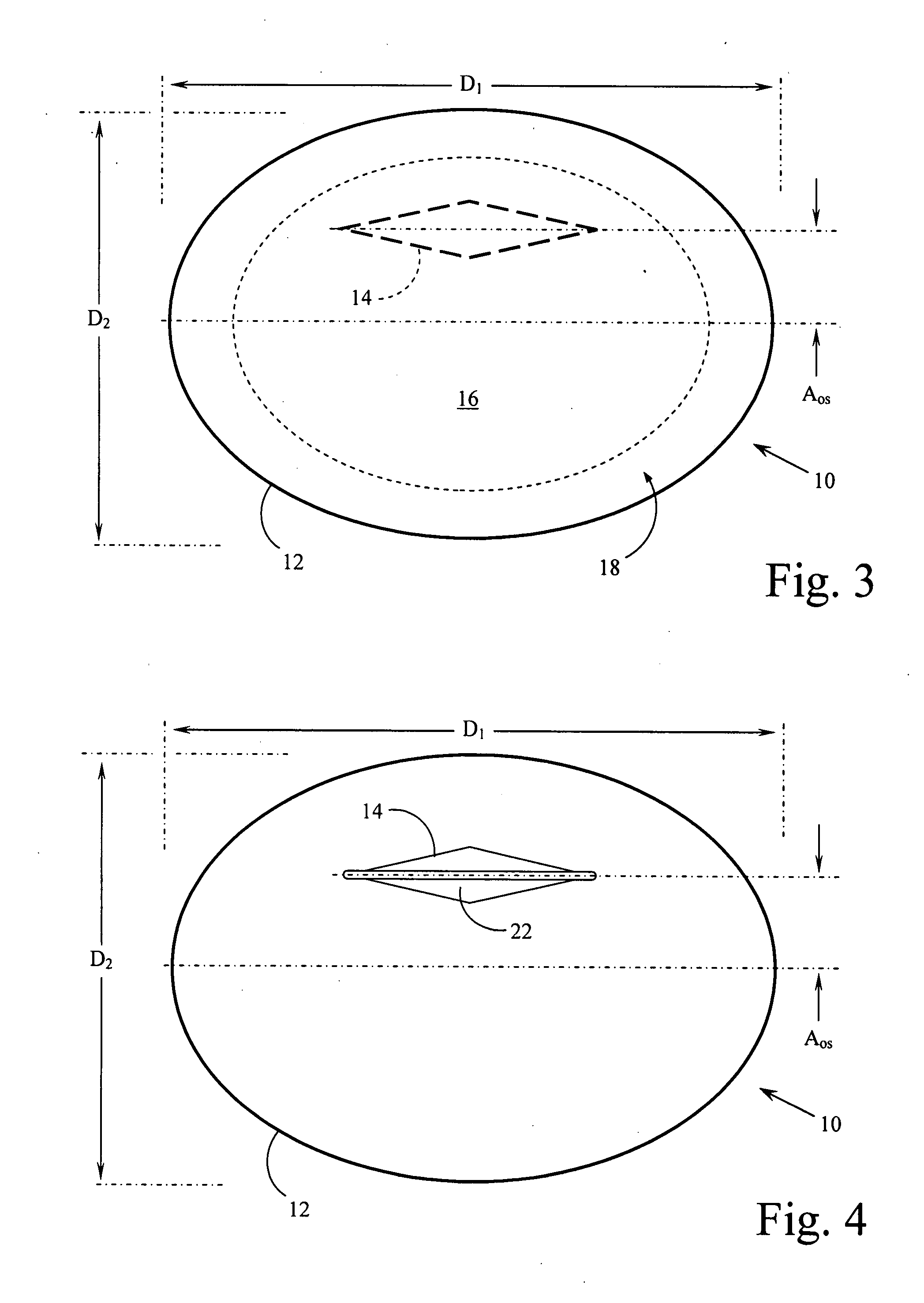
[0023]Reference is made first to FIG. 1 for a detailed description of the overall structure of the implant device of the present invention. As indicated above, specific structural features of the implant device of the present invention provide unique and beneficial characteristics to the device that facilitate the surgical placement of the device as well as the post-operative comfort of the patient. Implant device 10 as shown in FIG. 1 comprises two primary components, joint surface component 12 and stem component 14. Joint surface component 12 is a slightly elliptical, concave, surface platform that forms the new joint face for the prosthesis. Stem component 14 extends from the back face or back plane of joint surface component 12 and provides the mechanism whereby the implant is attached to the phalanx bone.

[0024]Joint surface component 12 is generally constructed with a concave profile to provide the contact surface for the first metatarsophalangeal joint. This surface constructi...


PUM


Abstract

An improved implant for use primarily within the first metatarsophalangeal joint. The implant includes an elliptical, concave, joint surface positioned on a stem and is designed to be placed into a prepared proximal face of the phalanx. The implant is sized according to the patient and may be provided in a number of standard incremental sizes. The improvements relate primarily to the structure, size, and position of the stem that extends into the phalanx to support the implant. The stem is off-set from a center axis of the elliptical joint surface. This off-center placement allows for a longer stem. Single deep indentations on each side of the stem facilitate retention within the bone. A size selection tool is provided to facilitate the selection and placement of an appropriately sized implant. The tool further provides a template for positioning and placing the stem in the phalanx. A method for sizing and selecting the appropriate implant, and positioning and fixing the implant as a partial joint replacement, especially for the first metatarsophalangeal joint, is also described.

Description

BACKGROUND OF THE INVENTION[0001]1. Field of the Invention[0002]The present invention relates generally to prosthetic medical implant devices, especially those associated with surgical joint replacement. The present invention relates more specifically a partial joint replacement implant for the bones of the human foot, especially the first metatarsophalangeal joints.[0003]2. Description of the Related Art[0004]Prosthetic implant devices have been used for some time to fully or partially replace existing skeletal joints in humans. Among the many joints associated with the bones of the human foot, one that is known to cause frequent problems is the metatarsophalangeal joint between the first metatarsal and the first phalanx in what is commonly known as the hallux or great toe. A number of efforts have been made in the past to partially or fully replace this joint. Some efforts have focused on the partial replacement of the joint using silicone based materials to construct a prosthetic...

Claims


Application Information

Patent Timeline
IPC IPC(8): A61F2/42
CPCA61F2/4225A61F2002/4659A61F2002/4233
Inventor GRASER, ROBERT
Owner LOWE JOHN PATRICK TRUSTEE CHAPTER 7 CASE NO 09 51026 C IN THE UNITED STATES BANKRUPTCY COURT FOR THE WESTERN DISTRICT OF TEXAS SAN ANTONIO DIV
Learn More