Control method, control system, and program

Active Publication Date: 2008-09-11
NIKON CORP
View PDF19 Cites 21 Cited by
  • Summary
  • Abstract
  • Description
  • Claims
  • Application Information

AI Technical Summary

Benefits of technology

[0022]The computer in which this program is installed repeatedly executes a predetermined measurement at least one of at a set timing and at set intervals and obtains data related to a predetermined performance of a predetermined apparatus and data on variation factors of the performance. Then, the computer performs multivariate analysis based on the obtained data, and derives a model equation used to predict a variation amount of the performance that includes at least one of the variation factors as a variable. Therefore, after the model equa

Problems solved by technology

In the case periodic exposure, development, measurement of a resist image and the like are performed for the check of the best focus position, however, the measurement takes a long period of time

Method used


Image

  • Control method, control system, and program
  • Control method, control system, and program
  • Control method, control system, and program

Examples


Example

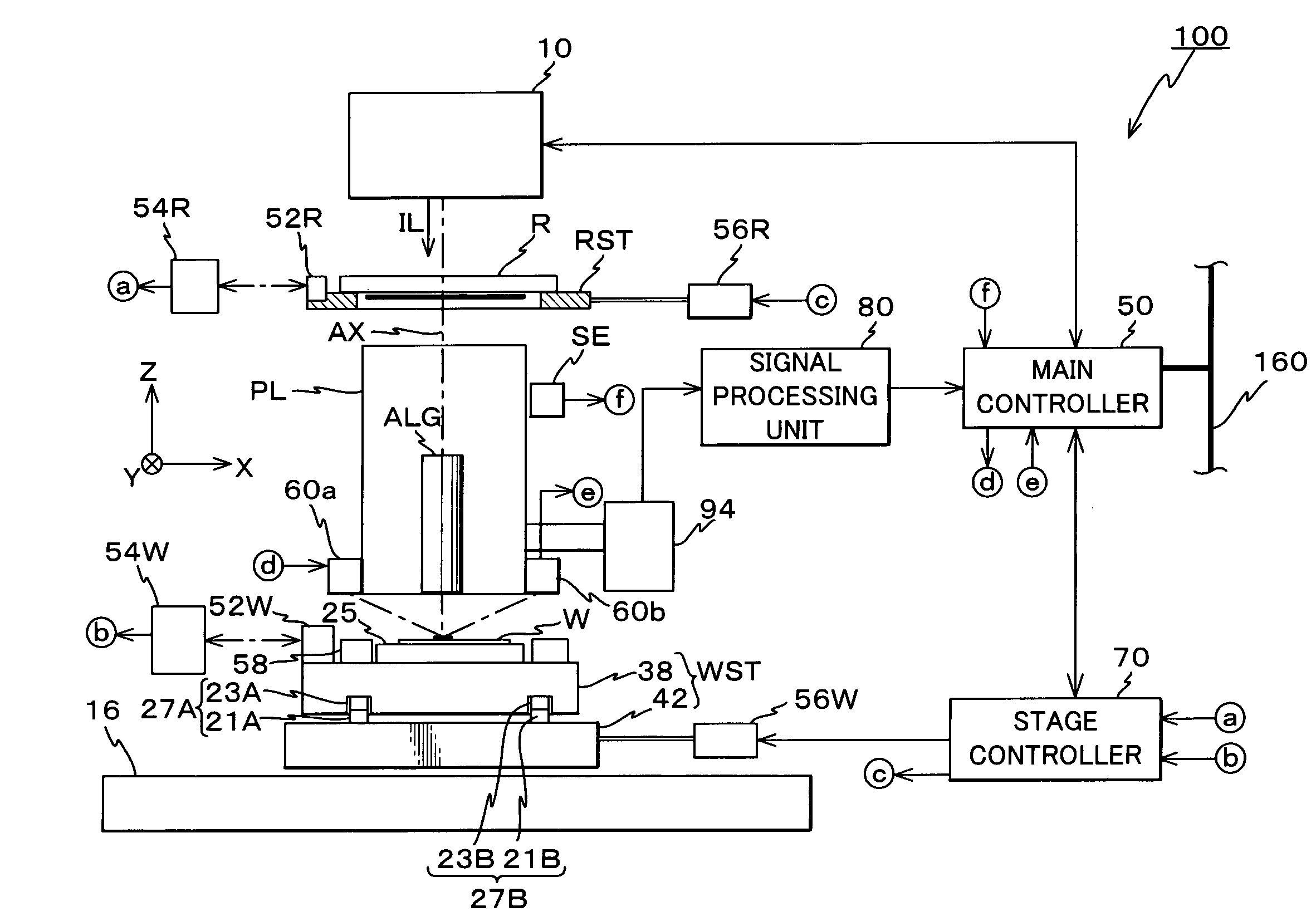
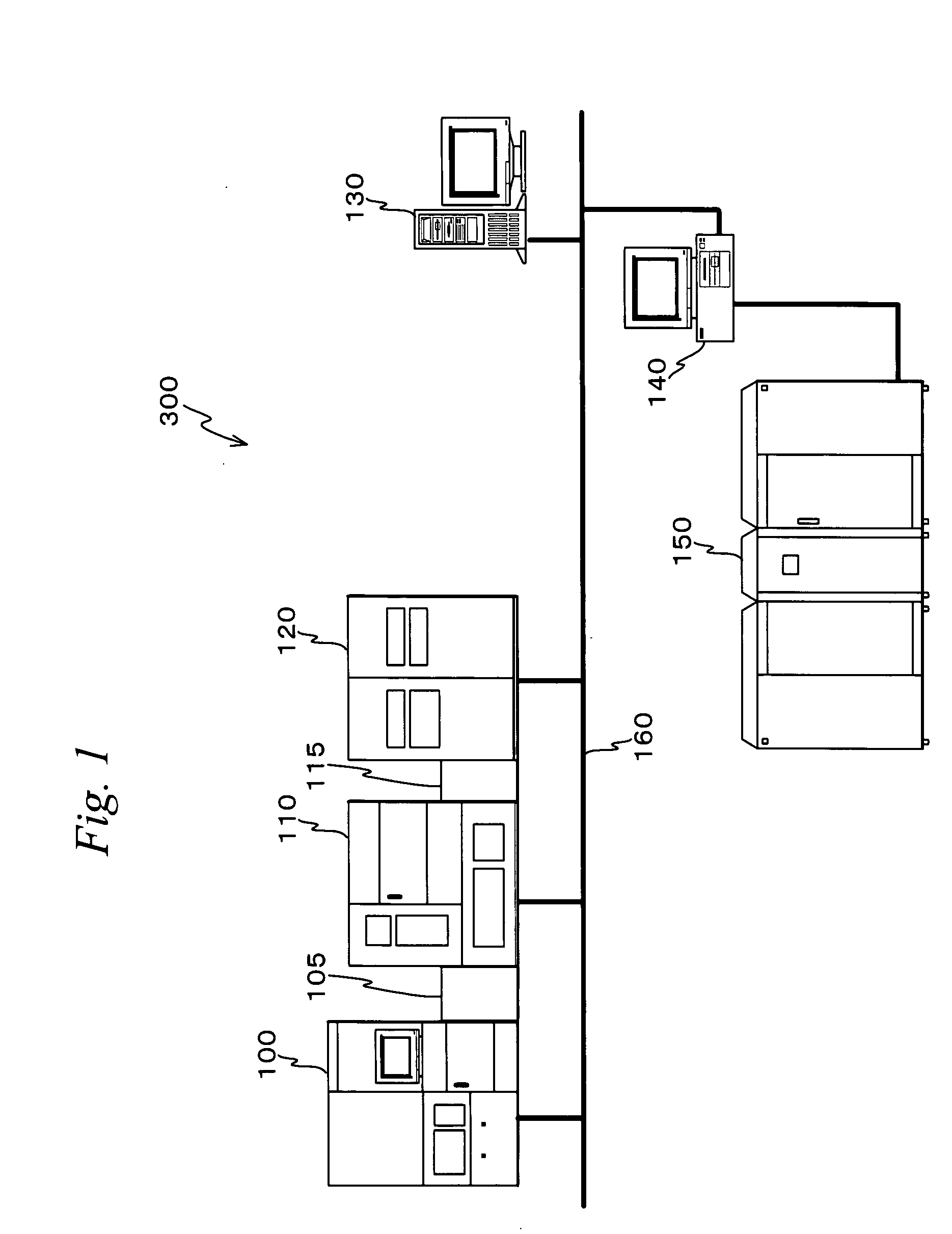
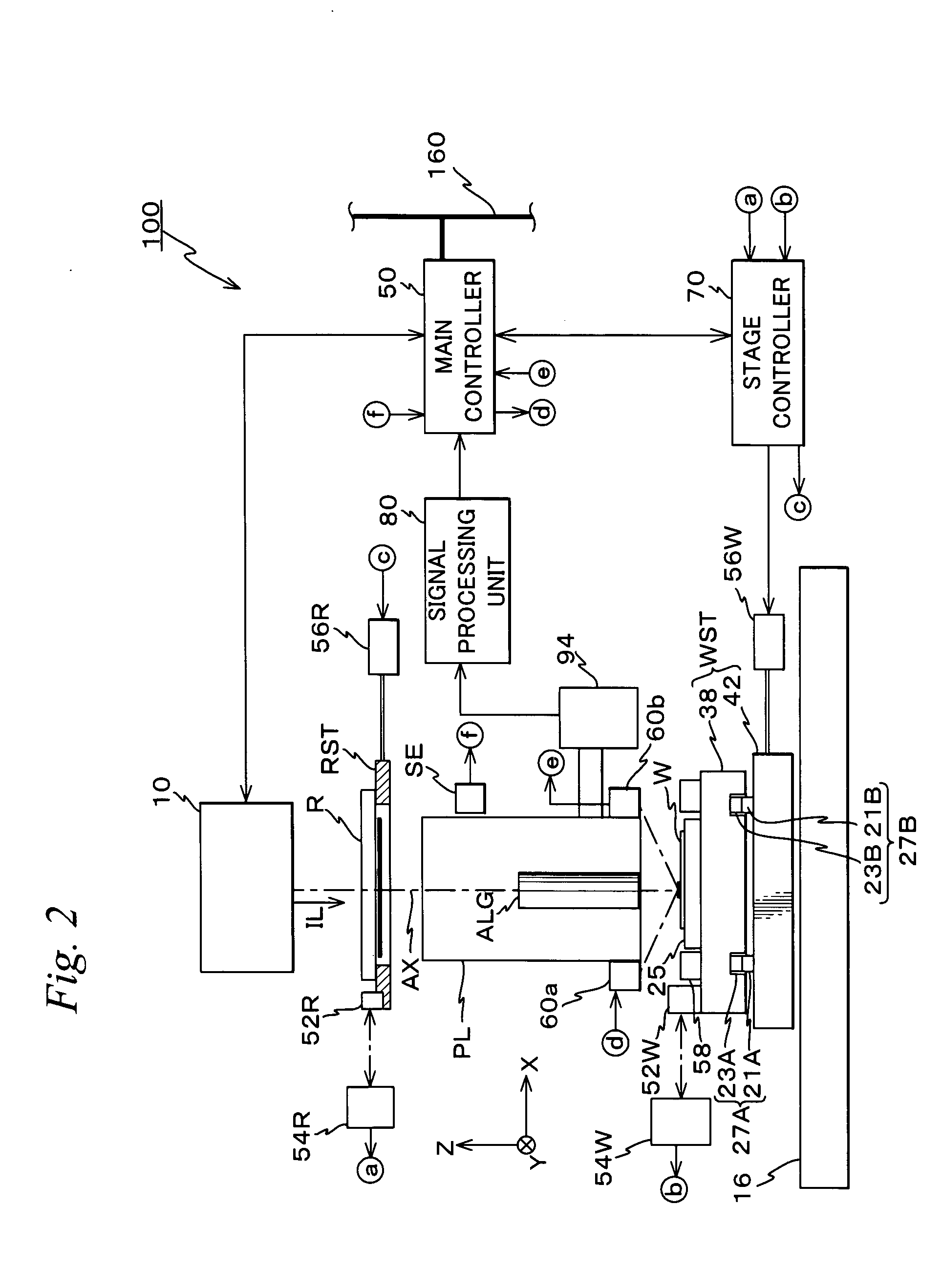
[0030]An embodiment of the present invention will be described based on FIGS. 1 to 5B. FIG. 1 schematically shows the entire configuration of a lithography system 300 in which a control method related to an embodiment is implemented.

[0031]Lithography system 300 is equipped with an exposure apparatus 100, a coater developer (hereinafter shortened to a ‘C / D’) 110 that connects in-line to exposure apparatus 100, an overlay measurement unit 120 that connects in-line to exposure apparatus 100 via C / D 110 and used also as an image measurement unit, a control server 130, a terminal server 140, a host computer 150 and the like. Exposure apparatus 100, C / D 110, overlay measurement unit 120, control server 130 and terminal server 140 connect to one another via a local area network (LAN) 160. Further, host computer 150 connects to LAN160 via terminal server 140. That is, in a hardware configuration, a communication path is secured between exposure apparatus 100, C / D 110, overlay measurement un...


PUM


Abstract

By repeatedly executing a predetermined measurement at set intervals, data on a predetermined performance (a best focus position) of a predetermined apparatus and data on variation factors of the performance are obtained (Steps 204 to 214). Based on the obtained data, multivariate analysis is performed and a model equation that is used to predict a variation amount of the performance and includes at least one of the variation factors as a variable is derived (Step 214). Therefore, after deriving the model equation, a variation amount of the performance can be predicted using the model equation by obtaining data on the variation factor that serves as the variable (Step 238). Accordingly, it becomes possible to maintain the performance described above with good accuracy in accordance with the prediction results and also optimize the implementation timing of maintenance and the like.

Description

CROSS-REFERENCE TO RELATED APPLICATIONS[0001]This application is a continuation of International Application PCT / JP2005 / 011727, with an international filing date of Jun. 27, 2005, the disclosure of which is hereby incorporated herein by reference in its entirety, which was not published in English. This non-provisional application also claims the benefit of Provisional Application No. 60 / 717,328 filed Sep. 15, 2005, the disclosure of which is hereby incorporated herein by reference in its entirety.BACKGROUND OF THE INVENTION[0002]1. Field of the Invention[0003]The present invention relates to control methods, control systems and programs, and more particularly to a control method and a control system that control the performance of a predetermined apparatus, and a program that makes a computer that controls the performance of the predetermined apparatus execute a predetermined procedure.[0004]2. Description of the Background Art[0005]Conventionally, in a lithographic process for man...

Claims


Application Information

Patent Timeline
IPC IPC(8): G05B13/04G03F7/207H01L21/02H01L21/027
CPCG03F7/705G03F7/7085G03F7/70641G03F7/70533
Inventor ISHII, YUUKIOKITA, SHINICHI
Owner NIKON CORP
Why Eureka
Try Eureka