Apparatus and method for detecting and identifying ferrous and non-ferrous metals

a technology of ferrous metals and detectors, applied in the field of metal detectors, can solve the problems of insufficient reliability of ferrous metal identification, inability to meet the demands of the market place, and complex methods used to separate them, so as to achieve the shortest recovery time and reliably identify ferrous and non-ferrous targets.

Inactive Publication Date: 2008-09-18
DIENCO
View PDF4 Cites 24 Cited by
  • Summary
  • Abstract
  • Description
  • Claims
  • Application Information

AI Technical Summary

Benefits of technology

[0091]It is an object of the present invention to provide a metal detector that reliably identifies ferrous and non-ferrous targets.
[0092]It is another object of the invention to provide a metal detector whose capability of distinguishing between ferrous and non-ferrous targets is unaffected by the medium surrounding the target or the distance at which the target is found
[0093]It is another objective of the present invention to provide a detector whose activation threshold is not subject to variation owing to the influence of magnetic minerals surrounding the target.
[0094]It is yet another

Problems solved by technology

More than 80 patents claim to have solved the problems inherent in such detectors, but the improvements in the art have been introduced in such small increments that a level of performance that satisfies the demands of the market place has not yet been attained.
The difficulties encountered by the state-of-the-art detectors stem from the fact that the resistive and reactive components of the signal intercepted by the receiver coil are intermingled and the various methods used to separate them are very complex and the results obtained are not good enough to achieve reliable identification of ferrous metals.
However, his system fails to differentiate between signals of different origins, the effect of which will be discussed below in further detail.
In the balanced condition, discrimination between ferrous and non-ferrous targets is possible, however, presence of magnetic minerals in the ground often causes misidentification of a target.
The detector can not determine whether this is caused by a target, or a change in the soil.
Attempts to separate the target signal from the background signal have resulted in the design of detectors which use multiple operating frequencies and process the resulting signals with extremely complicated circuits.
The drawbacks of such methods are obvious when one considers the problems of alignment, power consumption and drift of complex systems, under the temperature and humidity conditions that metal detectors are expected to endure.
This expedient greatly reduces a detector's sensitivity to magnetic minerals in the soil, but it also eliminates the detector's ability to discriminate between ferrous and non-ferrous targets.
Owing to the possibility of cancelling out a target, this method

Method used


Image

  • Apparatus and method for detecting and identifying ferrous and non-ferrous metals
  • Apparatus and method for detecting and identifying ferrous and non-ferrous metals
  • Apparatus and method for detecting and identifying ferrous and non-ferrous metals

Examples


Embodiment Construction

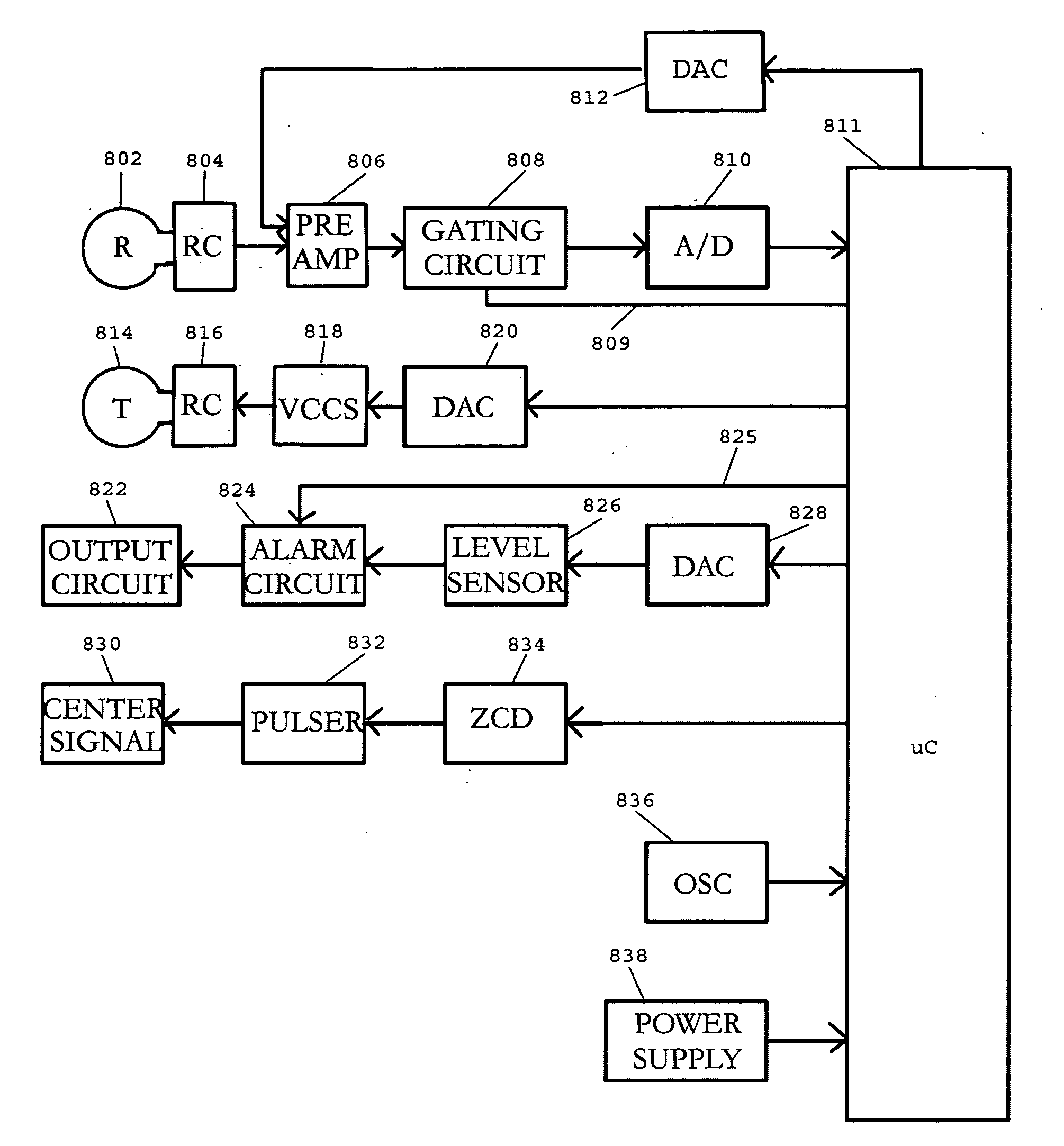
[0212]FIG. 8 shows a block diagram of the preferred embodiment of the invention. Receiver coil 802 is connected to the input of preamplifier 806 which feeds an amplified signal to gating circuit 808. The output of the gating circuit is connected to analog-to-digital converter 810, which interfaces with microcontroller 811. The gating pulses for circuit 808 are generated by the processor 811 and delivered via connection 809.

[0213]R-C network 804 provides critical damping of the receiver coil

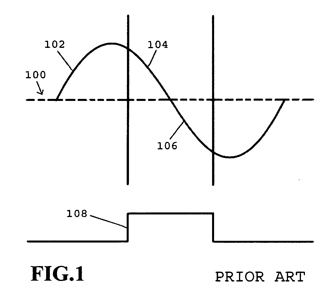
[0214]Processor 811 feeds a digitally stored waveform to digital-to-analog converter 820 and the corresponding analog signal is fed to voltage-controlled current source 818, which energizes transmitter coil 814. The shape of the current wave form is shown in FIG. 3-A

[0215]The transmitter coil is terminated by R-C network 816, to minimize oscillations following an abrupt change in the coil current. In conjunction with a low transmitter coil inductance, the component parameters in the voltage-contro...


PUM


Abstract

A metal detector using a linear current ramp followed by an abrupt current transition to energize the transmitter coil. The constant emf imposed on the target during the current ramp permits separation of transient voltages generated in response to eddy currents in the target and its environment from the voltages arising as a result of an inductive imbalance of the coil system The temporal separation of the various voltages makes reliable differentiation between ferrous and non-ferrous targets possible.

Description

CROSS-REFERENCE TO RELATED APPLICATONS[0001]This application claims the benefit of U.S. provisional application No. 60 / 611,070, filed on Sep. 15, 2005, which is incorporated herein, by reference in its entirety.BACKGROUND OF THE INVENTION[0002]This invention relates to metal detectors, and specifically to detectors that discriminate between ferrous and non-ferrous metals.[0003]Discriminating metal detectors are well known. More than 80 patents claim to have solved the problems inherent in such detectors, but the improvements in the art have been introduced in such small increments that a level of performance that satisfies the demands of the market place has not yet been attained.[0004]Discrimination is said to be functional “if ground permits” or “if the signal is not too weak”. Graphical representations of the state-of-the-art discrimination capability show that it is operative to a target depth that amounts to less than a quarter of the maximal detection depth.[0005]The difficult...

Claims


Application Information

Patent Timeline
IPC IPC(8): G01V3/08
CPCG01V3/104
Inventor WESTERSTEN, ALLAN
Owner DIENCO
Why Eureka
Try Eureka