Sensor device

a technology of a sensor and a spherical body, which is applied in the field of sensor devices, can solve the problems of limiting the development of heat in the case of sources, in particular light sources, and reducing the service life of the source, so as to avoid temperature-induced oscillator fluctuations

Active Publication Date: 2008-09-18
CEDES AG
View PDF3 Cites 4 Cited by
  • Summary
  • Abstract
  • Description
  • Claims
  • Application Information

AI Technical Summary

Benefits of technology

[0028]In order to avoid temperature influences, temperature sensitive parts of the sensor device can also be thermally separated from the radiation source, in particular illumination. For example, a reference oscillator can be thermally insulated in order to avoid temperature induced fluctuations of the oscillator.
[0029]A receiver with a pixel array is fundamentally preferred for the sensor device. However, it is also possible to use a simple light detector, with, as it were, a pixel that is fully sufficient for undertaking a distance measurement.

Problems solved by technology

The limiting factor for the development of heat in the case of sources, in particular, light sources, is regularly the power fed to the source which, given a constant supply voltage, is proportional to a current through the source, for example a current on the semiconductor chip of a light emitting diode.
The higher the current, the greater the development of heat, and thus the shorter the service life.

Method used


Image

  • Sensor device
  • Sensor device

Examples


Embodiment Construction

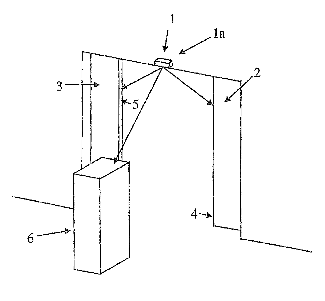
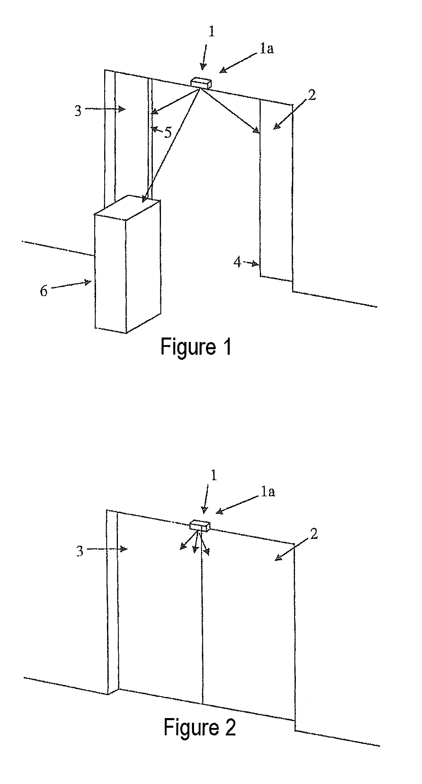
[0033]FIG. 1 shows an optical door sensor arrangement 1 on a two-leaf sliding door with an optical sensor 1a above the two door leaves. The door leaves 2, 3 are partially open and about to close. An object 6, for example a person, is moving toward the door leaves 2, 3.

[0034]The door sensor arrangement 1 detects the distance from the object 6 and, in particular, to the front edges 4, 5 of the door leaves 2, 3. Particular interest is accorded the distance of the object 6 from the front edges 4, 5 of the door leaves, in order to decide whether the closing operation is to be stopped, if appropriate.

[0035]This can be the case when the object 6 approaches the doors 2, 3 so close that a collision with the doors cannot be excluded.

[0036]The door sensor arrangement 1 operates according to the above described time of flight principle. In order to be able to undertake detection of the distances from the object 6 and the door front edges 4, 5, a light source emits light with a comparatively hig...


PUM


Abstract

A sensor device including a source for electromagnetic radiation, a receiver and a control device, the control device being designed for emitting electromagnetic radiation by means of the source and for determining a distance that is covered by the electromagnetic radiation emitted by the source from a reflection surface of an object to the receiver, doing so by evaluating a propagation time of the radiation or a phase of an oscillation modulated onto the radiation. According to the invention, the control device provides an economy mode in which the power of the source is lower in a prescribed time interval by comparison with a normal object detection mode, means being provided to ensure switching back into the normal object detection mode in the event of a predefined object situation.

Description

CROSS REFERENCE TO RELATED APPLICATIONS[0001]This application is a continuation of International Application No. PCT / EP2006 / 006284, filed Jun. 29, 2006, and claims the benefit under 35 USC 119(a)-(d) of German Application No. 10 2005 040 763.3, filed Aug. 26, 2005, the entireties of which are incorporated herein by reference.FIELD OF THE INVENTION[0002]The invention relates to a sensor device comprising a source for electromagnetic radiation, a receiver and a control device.BACKGROUND OF THE INVENTION[0003]Embodiments of optical sensors have become known in which the distance from an object is determined optically using the time of flight (TOF) method. In this case, an oscillation is modulated onto light emitted from a light source. Moreover, a sensor is provided with which the modulated light be can be detected when it is retro reflected from a corresponding object surface. The distance from the object at which the light has been retro reflected can be determined from the phase dif...

Claims


Application Information

Patent Timeline
Patent Type & Authority Applications(United States)
IPC IPC(8): G01C3/08
CPCG01S7/4008G01S7/497E05F15/73E05Y2400/322E05Y2400/452G01S13/04
Inventor ALBERS, BASDE COI, BEAT
Owner CEDES AG
Why Eureka
Try Eureka