Fiber laser arrangement with regenerative pulse amplification

a fiber laser and regenerative amplifier technology, applied in the direction of lasers, laser details, electrical equipment, etc., can solve the problems of destroying optical elements, affecting the performance of lasers, so as to reduce the effect of reducing the complexity of the apparatus and achieving the highest possible energy

Inactive Publication Date: 2008-09-18
JENOPTIK OPTICAL SYST
View PDF6 Cites 6 Cited by
  • Summary
  • Abstract
  • Description
  • Claims
  • Application Information

AI Technical Summary

Benefits of technology

The invention is about a new method for generating regeneratively amplified femtosecond pulses that reduces the complexity of the apparatus required and minimizes the detrimental effects of nonlinear effects. The method involves a fiber-laser arrangement with regenerative amplification that includes a femtosecond fiber oscillator, a fiber amplifier, a regenerative amplifier, and a pulse compression device. The fiber amplifier is designed to amplify and time-stretch the femtosecond pulses generated by the femtosecond fiber oscillator. The regenerative amplifier contains a disk-shaped laser crystal that provides additional pulse stretching during regenerative amplification. The method does not require a separate pulse stretching device and the stretching factors achieved with the regenerative amplifier are sufficient for regenerative amplification. The invention also includes a fast electro-optic switch to couple the preamplified and stretched pulses into the regenerative amplifier. The technical effects of the invention include reduced complexity, minimized nonlinear effects, and improved stability and efficiency of the regenerative amplification process.

Problems solved by technology

The amplification of femtosecond pulses in particular makes it necessary to deal with high pulse peak powers, which can lead to many types of detrimental effects during the amplification process, effects which limit the power scaling of a regenerative amplifier.
destruction of the optical elements.
Any higher-order dispersive effects which may occur can no longer be compensated under certain conditions, which means that the pulse compression can no longer be complete.

Method used


Image

  • Fiber laser arrangement with regenerative pulse amplification
  • Fiber laser arrangement with regenerative pulse amplification
  • Fiber laser arrangement with regenerative pulse amplification

Examples


Embodiment Construction

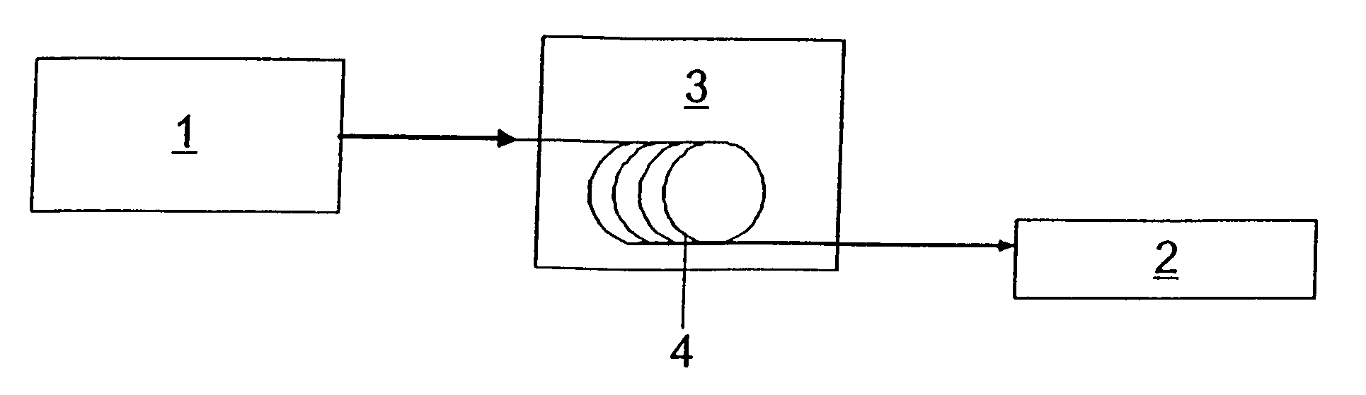
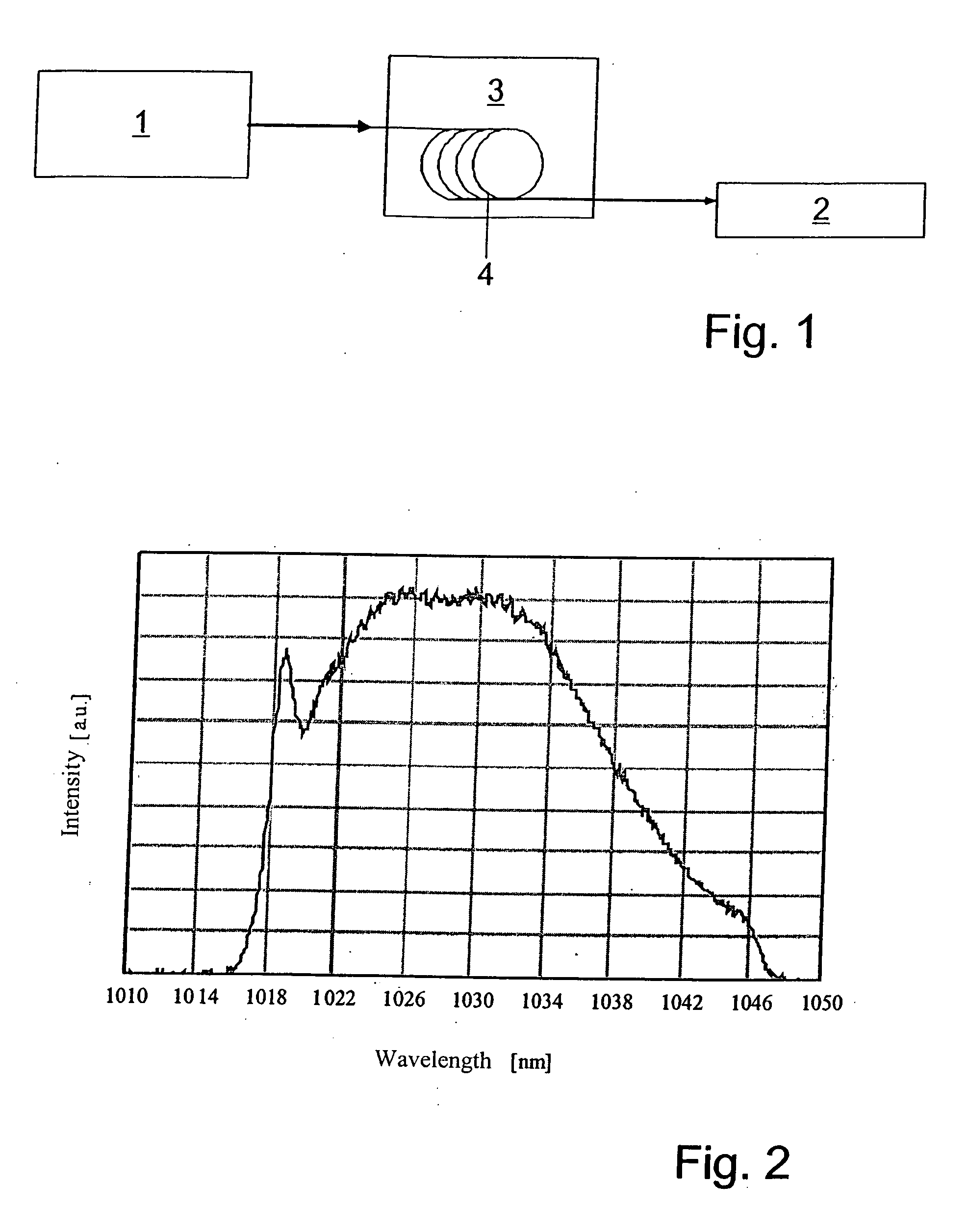
[0033]The fiber oscillator shown in FIG. 1 is a passive mode-locked femtosecond fiber oscillator 1 designed for parabolic pulse generation. This oscillator is intended to generate bandwidth-limited femtosecond pulses with typical pulse durations of 250 fs, pulse energies of several nanojoules, and a repetition rate of 50 MHz. The femtosecond fiber oscillator 1 with a central wavelength which lies at the point of maximum amplification of a regenerative amplifier 2 (1025 nm for Yb:KYW) consists of a ring resonator with conventional active (Yb) and passive fibers. The dispersion compensation in the resonator of the femtosecond fiber oscillator 1 is realized by means of a reflection grating. Femtosecond pulses with a pulse duration of Tin are generated in the femtosecond fiber oscillator 1 on the basis of the principle of parabolic pulse formation. Some of these are then coupled out by way of a fiber network and amplified in a fiber amplifier 3 with an amplifying fiber 4, which consists...


PUM


Abstract

A fiber laser arrangement with regenerative pulse amplification, having a femtosecond fiber oscillator as a pulse-generating unit, a fiber amplifier designed both as a pulse-amplifying and pulse-stretching device to amplify and to stretch the femtosecond pulses generated by the femtosecond fiber oscillator, a regenerative amplifier, which has a disk-shaped laser crystal as a gain medium, and which is designed to produce additional pulse stretching during the regenerative amplification, and a pulse compression device, which temporally compresses the amplified and time-stretched pulses.

Description

BACKGROUND OF THE INVENTION[0001]Regenerative amplifiers are used to achieve high pulse energies in the nanosecond, picosecond, and especially the femtosecond range (M. Leitner, K. Pachomis, D. Nickel, C. Stolzenburg, A. Giesen: “Ultrafast thin disk Yb:KYW regenerative amplifier with 200 kHz repetition rate”, OSA Trends in Optics and Photonics. Vol. 98, Advanced Solid-State Photonics, edited by Irina Sorokina and Craig Denman (Optical Society of America, Washington D.C., 2005), Article ME 5).[0002]Pulses generated by a femtosecond oscillator are coupled by means of rapid electro-optic elements into the regenerative amplifier, which is equipped with an gain medium, amplified by several passes through the gain medium, and coupled out after reaching the desired pulse energy.[0003]The amplification of femtosecond pulses in particular makes it necessary to deal with high pulse peak powers, which can lead to many types of detrimental effects during the amplification process, effects which...

Claims


Application Information

Patent Timeline
Patent Type & Authority Applications(United States)
IPC IPC(8): H01S3/00
CPCH01S3/0057H01S3/0604H01S3/067H01S3/06754H01S3/235H01S3/1618H01S3/1675H01S3/2316H01S3/094084
Inventor LEITNER, MARTIN
Owner JENOPTIK OPTICAL SYST
Why Eureka
Try Eureka