Chemical Analytic Apparatus and Chemical Analytic Method

Inactive Publication Date: 2008-09-18
JAPAN SCI & TECH CORP
View PDF8 Cites 67 Cited by
  • Summary
  • Abstract
  • Description
  • Claims
  • Application Information

AI Technical Summary

Benefits of technology

[0020]The dilution is basically performed by uniting the droplet that includes the magnetic ultrafine particles and a droplet for dilution, by using the same mechanism as the reaction unit. A magnification of dilution can be changed by controlling a volume ratio of droplet. As for the detection, a change of the specimen after the reaction is measured by using an optical method such as the absorption-light and light-emission. In addition, to improve a conveyance efficiency of the magnetic ultrafine particles that utilize for the conveyance of specimen, when the droplet is conveyed the magnetic ultrafine particles are cohered and moved, and the magnetic ultrafine particles are dispersed in the inside of droplet to hasten chemical reaction in the processes of reaction and dilution. As for this dispersion/cohesion method, the physical and chemical reactions by using a magnetic force, heat, light or pH are utilized. Also, in the reaction unit, a temperature control with a good accuracy can be performed by integrating a micro-heater and temperature sensor to a substrate if it is necessary.
[0021]As mentioned above, in the chemical analytic apparatus of the present invention, only

Problems solved by technology

However, the micro-channel and reactor of these are parts of the analytic apparatus, and because the other elements of fluidic machine etc such as a pump, valve etc are large as a conveyance system of liquid, a miniaturization of total system and a making low-cost are not realized yet (reference to Non-patent document 1 and Non-patent document 2).
Also, it in

Method used


Image

  • Chemical Analytic Apparatus and Chemical Analytic Method
  • Chemical Analytic Apparatus and Chemical Analytic Method
  • Chemical Analytic Apparatus and Chemical Analytic Method

Examples


Embodiment Construction

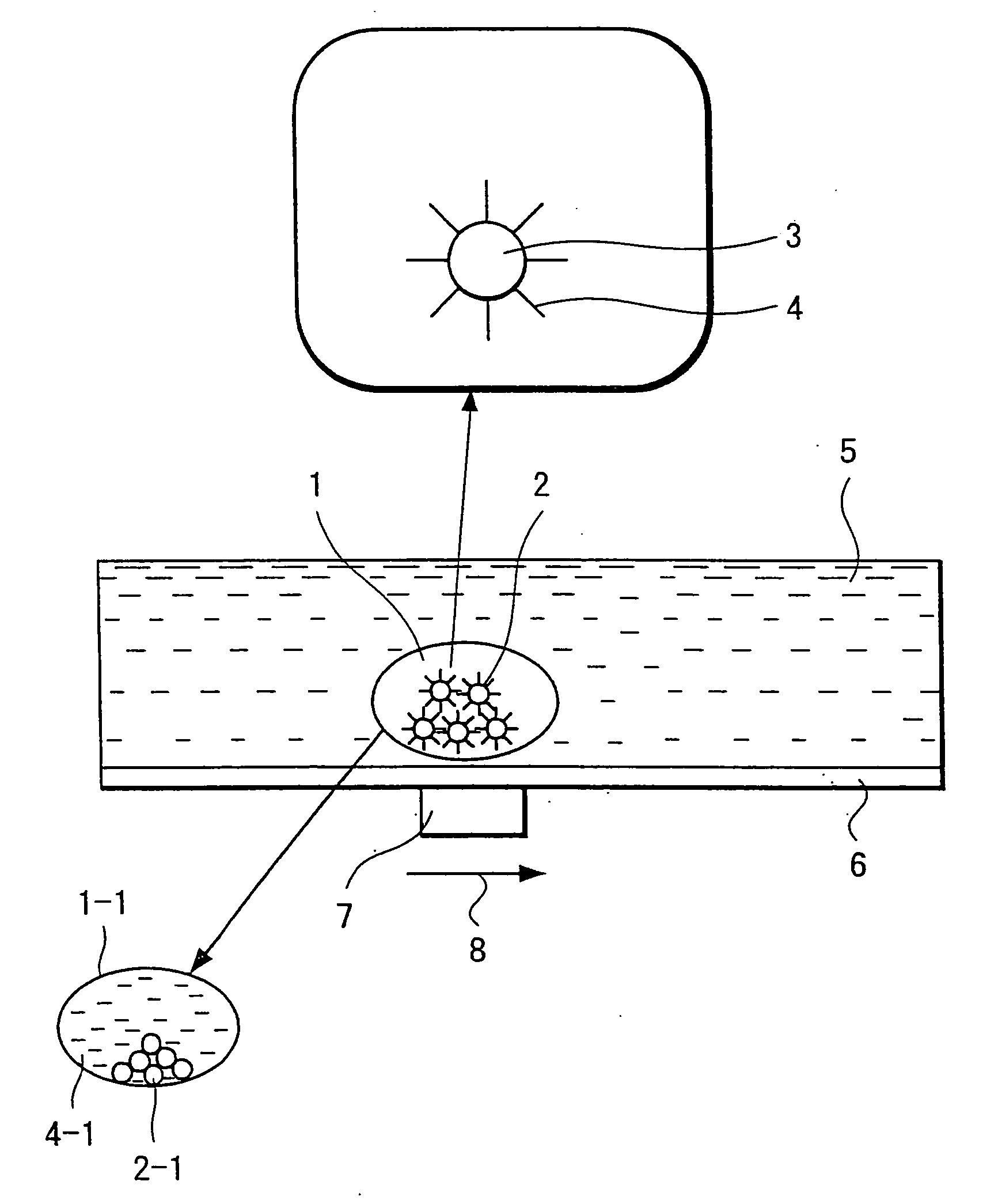
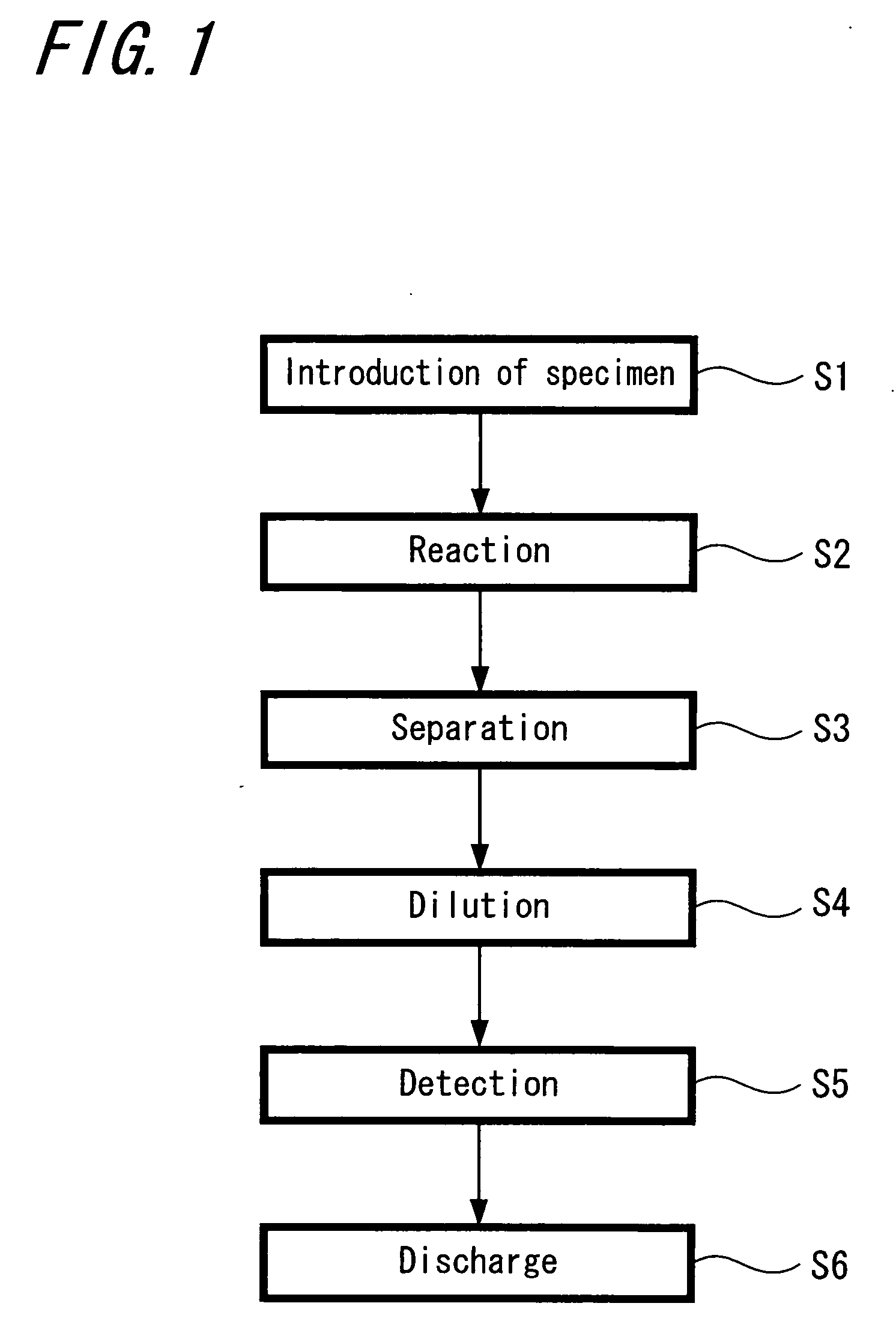
[0032]A flowchart of the processing of a specimen in a small sized chemical analytic apparatus according to the present invention is shown in FIG. 1.

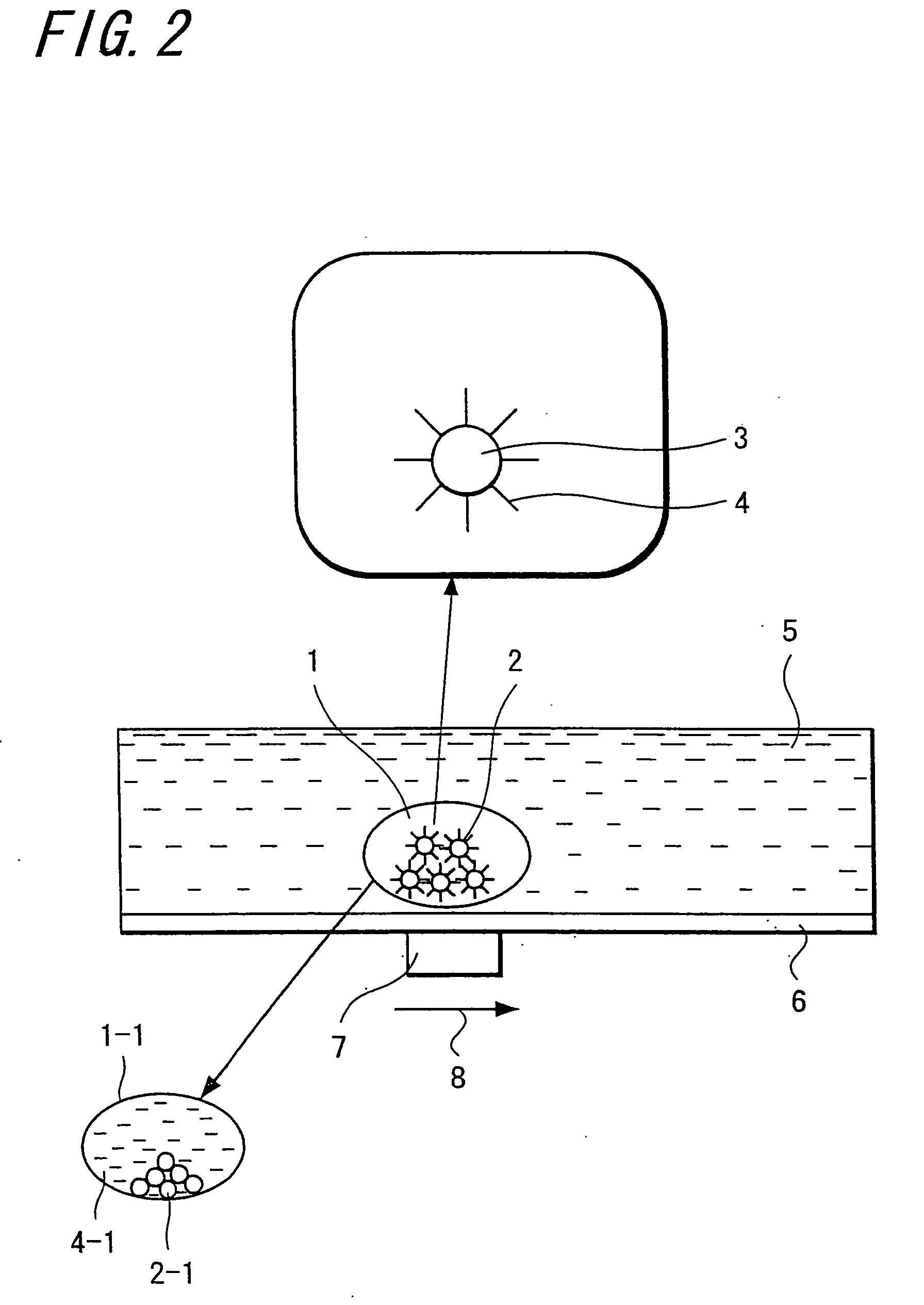
[0033]In FIG. 1, a droplet that is a specimen that includes magnetic ultrafine particles is introduced to an introduction unit by capturing and fixing the specimen to the surface of magnetic ultrafine particles such as magnetic beads (step S1). Subsequently, the droplet is conveyed to a reaction unit by the magnetic force, and it is mixed with a reactive reagent and a processing of reaction is performed (step S2). In this case, a temperature control is performed corresponding to the processing of reaction. Next, the droplet after the reaction is conveyed to a separation unit, and here, most of reactive solvent that became unnecessary and a minimum solvent that includes the magnetic ultrafine particles are separated (step S3). The droplet that includes the magnetic ultrafine particles is conveyed to a dilution unit and, in here, it is di...


PUM


Abstract

A chemical analytic apparatus of the present invention is the one which proposes that a miniaturization, a making low-cost and portability are possible and also the operation of each process of separation, concentration and dilution of specimen is possible, and which includes: an introduction means (S1) that introduces a droplet to which magnetic ultrafine particles are mixed into another liquid that differs from the droplet while maintaining a single droplet; a conveyance means by which the droplet that includes the magnetic particles is conveyed in another liquid of the introduction means by applying magnetic field externally to the magnetic ultrafine particles; and processing means (S2 to S6) by which operations for processing of chemical analysis are performed one by one in the process in which the droplet to which the magnetic ultrafine particles are mixed is conveyed by the conveyance means

Description

TECHNICAL FIELD[0001]The present invention is the one that relates to a chemical analytic apparatus and chemical analytic method that perform a chemical analysis by using a very small amount of a droplet.BACKGROUND ART[0002]From the past, a very small channel (or micro-channel) for separation and a reactor that aim to the chemistry, biochemical analysis and DNA array analysis are developed by using a micromachining technology to which a microfabrication technology for semiconductor was applied and developed (reference to Patent document 1, Non-patent document 1 and Non-patent document 2). Also a very small amount of droplet is operated by an electrical method, and an apparatus that performs a biochemical reactive operation of the very small amount of liquid is being proposed by this means (reference to Patent document 2, Non-patent document 3 and Non-patent document 4).[0003]Patent document 1: Japanese patent application H-13-132861.[0004]Patent document 2: Japanese patent applicati...

Claims


Application Information

Patent Timeline
IPC IPC(8): B01J19/08B01L3/00G01N35/10
CPCB01L3/502761B01L3/502784B01L3/502792Y10T436/11B01L2200/0673B01L2300/089B01L2400/043B01L2200/0647G01N35/00G01N35/10
Inventor SHIKIDA, MITSUHIROSATO, KAZUOHONDA, HIROYUKIINOUCHI, KOHTA
Owner JAPAN SCI & TECH CORP
Why Eureka
Try Eureka