

Polypropylene-Based Wire and Cable Insulation or Jacket
a technology of polypropylene and wire and cable, applied in the field of polypropylene-based wire and cable insulation or jacket, can solve the problems of requiring a considerable amount of additional time, affecting the overall process, and affecting the quality of the finished product,
- Summary
- Abstract
- Description
- Claims
- Application Information
AI Technical Summary
Problems solved by technology
Method used
Image

Examples
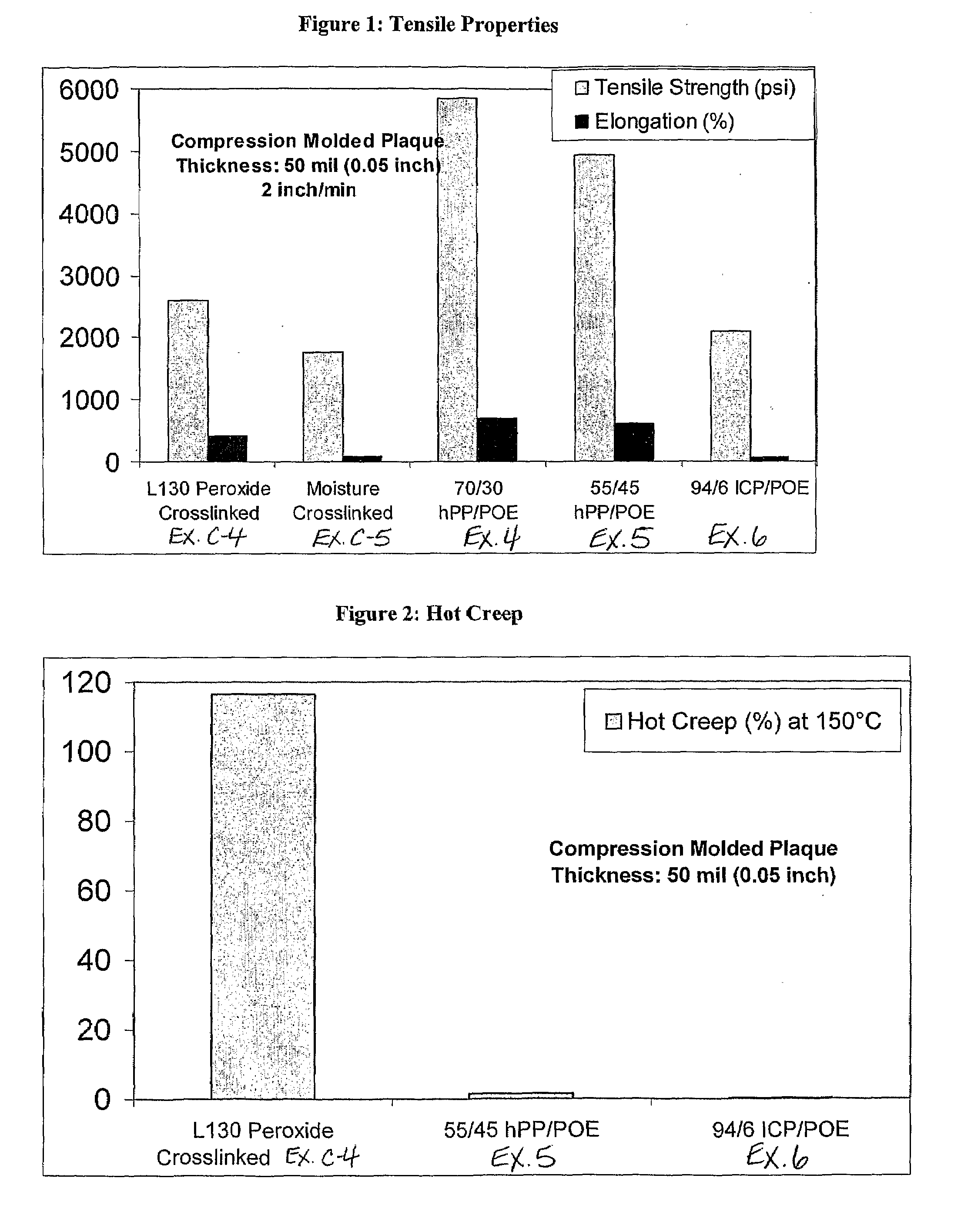
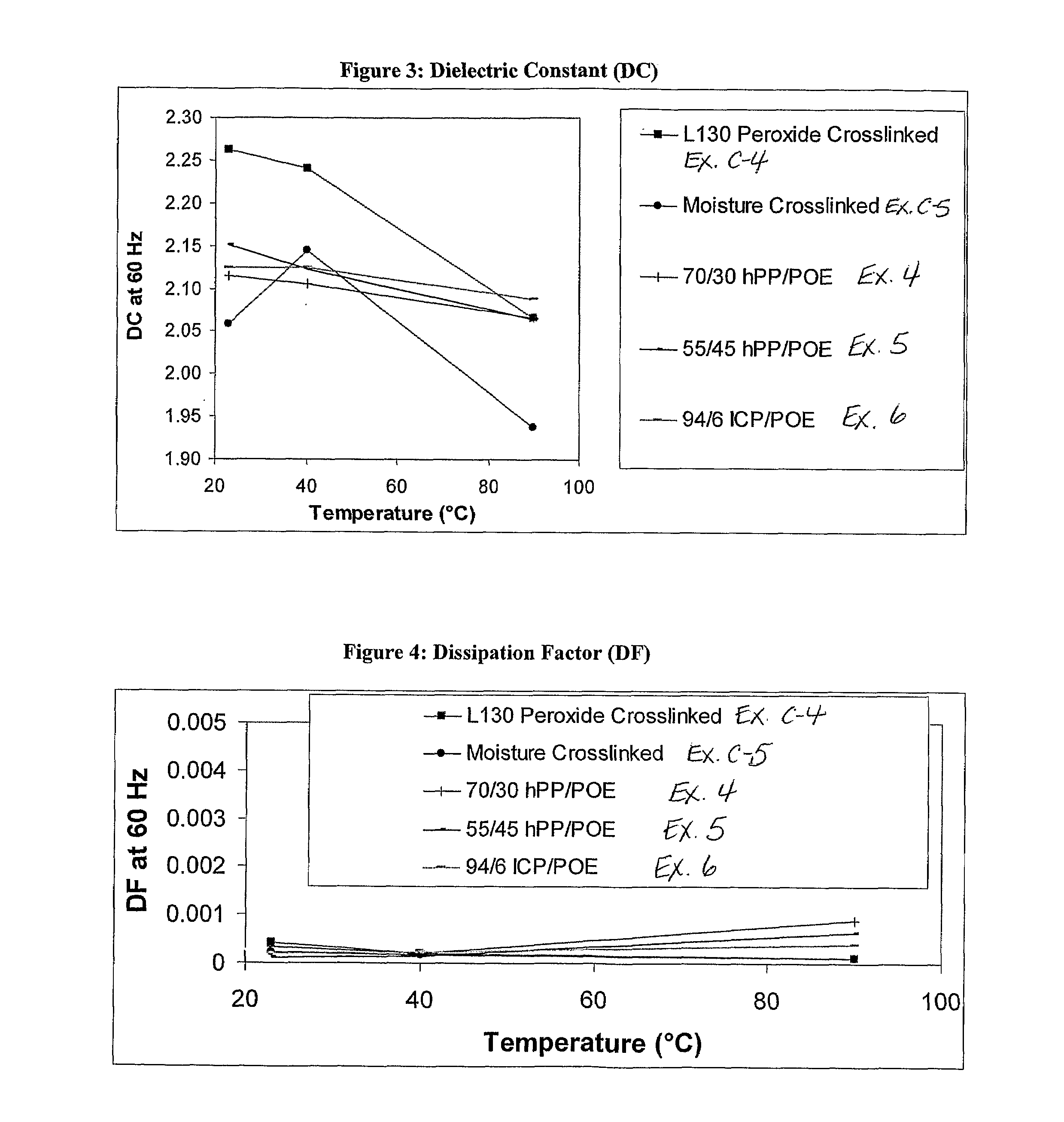
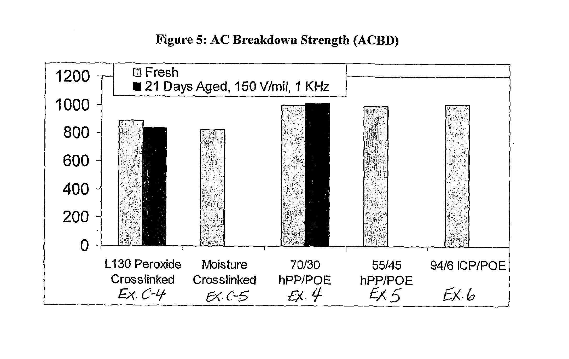
example 4
70 / 30 hPP / POE Blend
[0057]DOW H314-02Z propylene homopolymer (hPP, 70 wt %) and 30 wt % Affinity 8150 polyolefin elastomer (POE) were melt blended in a Banbury mixer at 180 C for 3.5 minutes, and passed through an extruder and then an underwater pelleter. Pellets from the pelleter were then collected and compression molded into 50 mil plaques at 170 C for 10 minutes. Five dog bone samples were cut from each plaque, and the samples were then measured for tensile strength, elongation, hot creep dielectric constant, dissipation factor, and measure alternating current breakdown strength. The results of these measurements are also reported in FIGS. 1-5.
example 5
55 / 45 hPP / POE Blend
[0058]DOW H314-02Z propylene homopolymer (137.50 g) and of Affinity 8150 (112.50 g) were added to a Brabender mixing bowl previously purged with nitrogen. After fluxing for 3 minutes at 170 C, 50 mil plaques were immediately compression molded at 170 C for 10 minutes. Seven dogbone samples were cut from each plaque, and measured for tensile strength, elongation, hot creep dielectric constant, dissipation factor, and measure alternating current breakdown strength. The results of these measurements are also reported in FIGS. 1-5.
example 6
94 / 6 ICP / POE
[0059]DOW 7C54H impact copolymer polypropylene (235 grams) and of Affinity 8150 (15 g) were added to a Brabender mixing bowl previously purged with nitrogen. After fluxing for 3 minutes at 170 C, 50 mil plaques were immediately compression molded at 170 C for 10 minutes. Seven dogbone samples were cut from each plaque, and measured for tensile strength, elongation, hot creep dielectric constant, dissipation factor, and measure alternating current breakdown strength. The results of these measurements are also reported in FIGS. 1-5.
[0060]In all instances, the compression molded plaques of the invention either met or exceeded the properties of the comparative example plaques.
PUM
| Property | Measurement | Unit |
|---|---|---|
| weight percent | aaaaa | aaaaa |
| density | aaaaa | aaaaa |
| mole percent | aaaaa | aaaaa |
Abstract
Description
Claims
Application Information