
Triphenyl phosphine oxide polymer capacitors

a polymer capacitor and triphenyl phosphine oxide technology, applied in the direction of capacitors, fixed capacitor details, multiple fixed capacitors, etc., can solve the problems of small dielectric constant, film forming difficulty, and great decrease in dielectric properties in humid atmospher

Inactive Publication Date: 2002-12-10
EIKOS
View PDF11 Cites 20 Cited by
  • Summary
  • Abstract
  • Description
  • Claims
  • Application Information

AI Technical Summary

Problems solved by technology

These conventional polymeric materials, however, have several disadvantages as a dielectric film material, including a great decrease in dielectric properties in a humid atmosphere, film forming difficulties, small dielectric constants, small energy storage density, and instability at increasingly high temperatures.
The large thickness of the polymer sheets in this case reduces the energy storage density of the capacitors.
Conventional polymer films cannot satisfy the requirement for the reduction of film thickness sufficiently, because a very thin film has poor workability or processability in the production step of capacitors.
In addition to the current need for thin film capacitors, persons skilled in the art are faced with many manufacturing limitations.
If the voltage of the capacitor is raised above the corona inception voltage, rapid degradation of the dielectrics can occur.

Method used


Image

  • Triphenyl phosphine oxide polymer capacitors

Examples


example 1

Dielectric testing

Dielectric testing was performed on the three TPPO polymers synthesized and prepared as described above. The dielectric constant was calculated using the measured values of capacitance (C), thickness (T) and electrode area (A) and by applying the following classic equation for capacitance:

C=-.sub.o.kappa..sub.d (A / T), where -.sub.o =8.854.times.10.sup.-12 f / m

Solving for K.sub.d gives; .kappa..sub.d =(C T) / (-.sub.o A)

A precision micrometer was used to determine the thickness. The electrode diameter was measured using a hand held micrometer. All capacitance and dissipation measurements were performed using a Stanford Research Systems LCR meter (model SR715).

The characterization of these films consists of measuring dielectric constant (k is calculated from thickness and capacitance), and dissipation factor (DF) at several frequencies (120 Hz, 1 kHz, and 10 kHz). The dielectric constant and DF was characterized for all three films and the Mylar-C control films at room ...

example 2

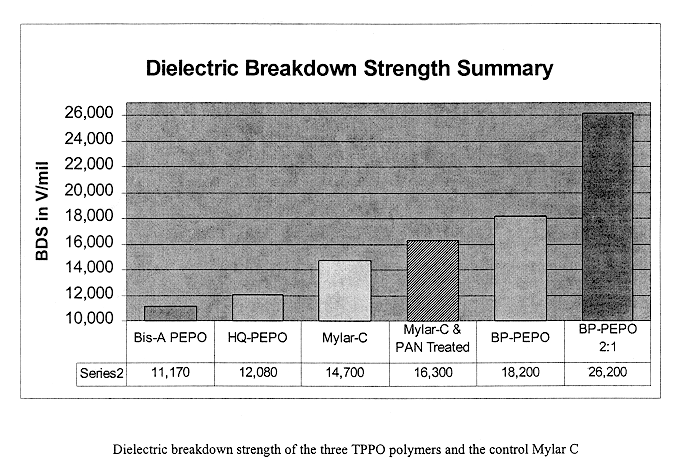
Breakdown Strength Measurement Results

A high voltage breakdown testing apparatus consisted of a polycarbonate test cell, High Voltage DC power supply, chart recorder, and a digital voltmeter with voltage divider for monitoring the test conditions, as specified under ASTM D149. The test cells were designed for testing metallized and plain films. The apparatus was tested using Mylar-C film ranging from 0.06 mil to 1.00 mill thickness and with complete dielectric properties data. These films were also used for the conducting polymer electrode experiments. The trials with the Mylar films consistently reproduced the results documented in the data sheets.

Breakdown testing is a bulk material property that is dependent on test apparatus and conditions like humidity. Therefore, breakdown testing was performed in series on the same day,for all samples and control samples, to reduce day to day variability.

Capacitors were fabricated from both the "as delivered" Mylar-C films and those specially...


PUM


Abstract

The present invention is a capacitor of a triphenyl phosphine oxide film as a base dielectric. More specifically, the base dielectric film is selected from the group consisting of Bisphenol-A (Bis-A PEPO). 4',4'-biphenol (BP-PEPO), and Hydroquinone (HQ-PEPO). TPPO based polymers have a very high breakdown strength, dielectric constant, low dissipation factor and high energy density. An ultra-thin coating can leverage the capabilities of this new dielectric, and potentially other commercial polymer films, to make possible energy storage in excess of 1 J / cc. The triphenyl phosphine oxide film can be fabricated containing a conducting PolyANiline (PAN) polymer layer located between the electrode and core polymer, or by being dip coated with PAN.

Description

1. Field of the InventionThe present invention relates to AB block co-polymers comprising, as the A component, a triphenyl phosphine oxide (TPPO) monomer and, as the B component, another monomer which may be the same or different, and to ultra-high density, low loss, thin film capacitors containing these AB block co-polymers.2. Description of the BackgroundMetallized film capacitors are utilized in a broad range of electrical and electronic components. Various dielectrics and different structures make these products suitable for versatile applications in automotive and entertainment electronics, telecommunications, and industrial and medical electronics (see U.S. Pat. Nos. 5,691,442; 6,040,416; 5,387,629; and 5,134,207).Metallized film capacitors are generally used to store energy. Some applications use capacitors to perform specific functions such as filtering, timing, and decoupling. The advantages of metallized film capacitors include high temperature operation, exceptional stabi...

Claims


Application Information

Patent Timeline
IPC IPC(8): H01G4/18H01G4/14
CPCH01G4/18
Inventor PICHE, JOSEPHMACK, PATRICKGLATKOWSKI, PAULCONROY, JEFFREYWINSOR, PAUL
Owner EIKOS
Learn More