Control device and method of controlling an internal combustion engine
- Summary
- Abstract
- Description
- Claims
- Application Information
AI Technical Summary
Benefits of technology
Problems solved by technology
Method used
Image

Examples
first embodiment
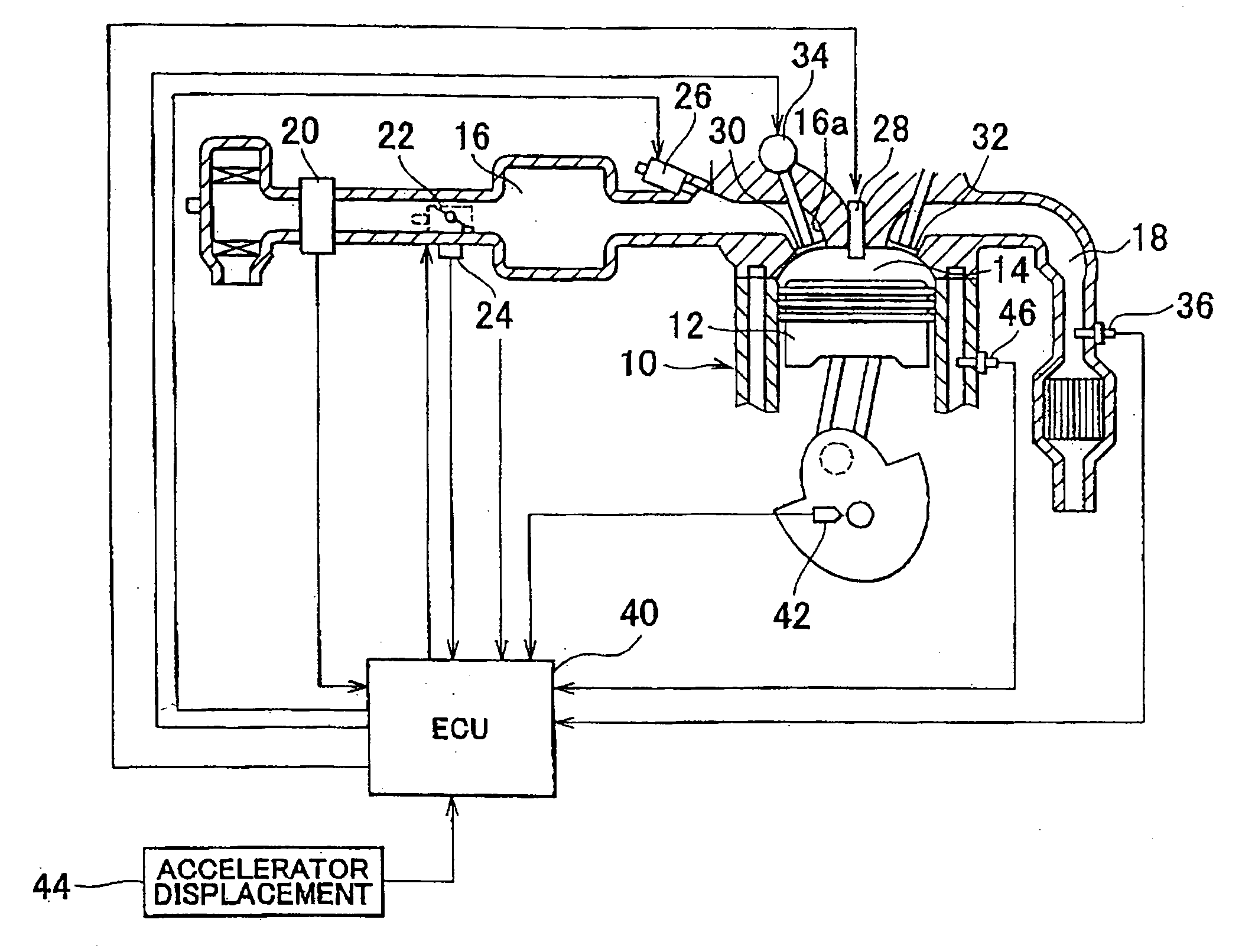
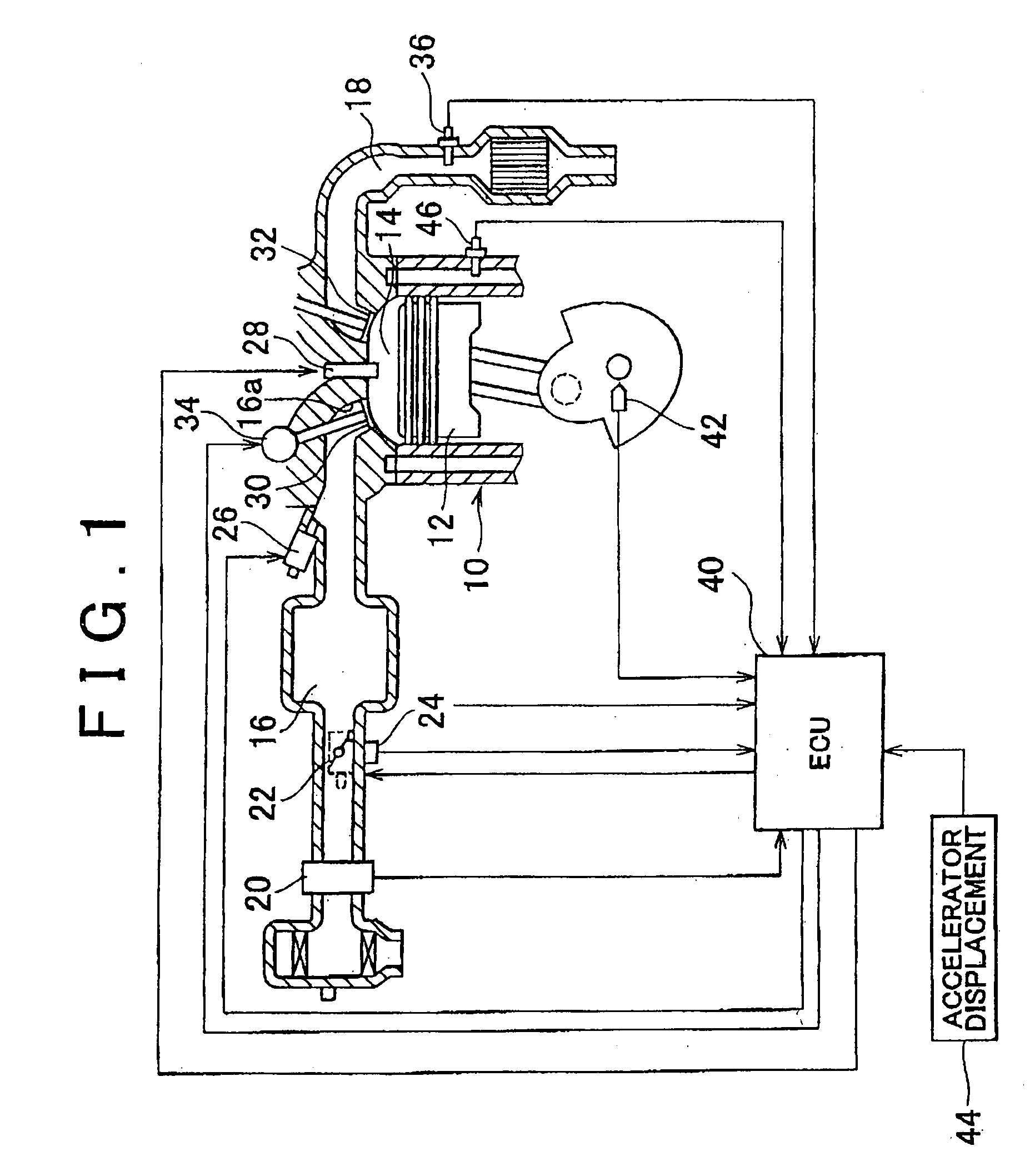
[0024]FIG. 1 is a diagram showing the configuration of the present invention. The configuration of the embodiment includes an internal combustion engine 10. A piston 12 is provided inside the cylinder of the internal combustion engine 10. The piston 12 can reciprocate inside the cylinder. Inside the cylinder of the internal combustion engine 10, a combustion chamber 14 is formed on the side of the top portion of the piston 12. Also, an intake passage 16 and an exhaust passage 18 communicate with the combustion chamber 14.
[0025]An airflow meter 20 that outputs a signal according to the flow rate of air sucked into the intake passage 16 is provided near the inlet of the intake passage 16. A throttle valve 22 is provided downstream of the airflow meter 20. The throttle valve 22 is an electronically controlled throttle valve whose throttle opening can be controlled independently from the accelerator displacement. Arranged near the throttle valve 22 is a throttle position sensor 24 that ...
second embodiment
[0049]Next, the present invention will be described with reference to FIGS. 5A to 8. In this embodiment, the configuration shown in FIG. 1 is employed, and the ECU 40 executes the operation shown in FIG. 6, described later, instead of the operation shown in FIG. 3.
[0050]In this embodiment as well, basically in the same manner as in the first embodiment described above, the ECU 40 closes the throttle valve 22 during cold acceleration to generate a negative intake pipe pressure according to the engine coolant temperature, and also controls the duration and the lift of the intake valve 30 so that the intake air amount Ga becomes the requested intake amount.
[0051]However, if cold acceleration is sudden, the requested intake amount changes abruptly. In that case, there may be times when the requested intake amount cannot be provided due to restriction on the operating speed of the variable valve mechanism 34, that is the actuator that varies the duration and the lift of the intake valve ...
third embodiment
[0061]Next, the present invention will be described with reference to FIGS. 9A to 9G and FIG. 10. In this embodiment, the configuration shown in FIG. 1 is employed, and the ECU 40 executed the operation shown in FIG. 10, described later, instead of the operation shown in FIG. 3.
[0062]In this embodiment as well, basically in the same manner as in the first embodiment described above, the ECU 40 closes the throttle valve 22 during cold acceleration to produce a negative intake pipe pressure according to the engine coolant temperature, and also controls the duration and the lift of the intake valve 30 so that the intake air amount Ga becomes the requested intake amount.
[0063]However, when the level of a requested negative intake pipe pressure to be produced by closing the throttle valve 22 during cold acceleration is high, there may be times when the requested negative intake pipe pressure cannot be provided due to the restriction on the operating speed of the throttle valve 22, so an ...
PUM
 Abstract
Description
Claims
Application Information
 - R&D
- Intellectual Property
- Life Sciences
- Materials
- Tech Scout
- Unparalleled Data Quality
- Higher Quality Content
- 60% Fewer Hallucinations
Browse by: Latest US Patents, China's latest patents, Technical Efficacy Thesaurus, Application Domain, Technology Topic, Popular Technical Reports.
© 2025 PatSnap. All rights reserved.Legal|Privacy policy|Modern Slavery Act Transparency Statement|Sitemap|About US| Contact US: help@patsnap.com