Indirect rotor resistance estimation system and method

Active Publication Date: 2008-09-18
GE HYBRID TECH
View PDF8 Cites 5 Cited by
  • Summary
  • Abstract
  • Description
  • Claims
  • Application Information

AI Technical Summary

Benefits of technology

[0010]It is therefore an object of this invention to provide an improved ind

Problems solved by technology

DTC, however, also presents some drawbacks compared to FOC, such as high current ripple, difficulty to control torque and flux at low speeds, high acoustic noise at low speed and lack of direct current control.
The difficulty with the above expression for slip is

Method used


Image

  • Indirect rotor resistance estimation system and method
  • Indirect rotor resistance estimation system and method
  • Indirect rotor resistance estimation system and method

Examples


Example

[0040]Aside from the preferred embodiment or embodiments disclosed below, this invention is capable of other embodiments and of being practiced or being carried out in various ways. Thus, it is to be understood that the invention is not limited in its application to the details of construction and the arrangements of components set forth in the following description or illustrated in the drawings. If only one embodiment is described herein, the claims hereof are not to be limited to that embodiment. Moreover, the claims hereof are not to be read restrictively unless there is clear and convincing evidence manifesting a certain exclusion, restriction, or disclaimer.

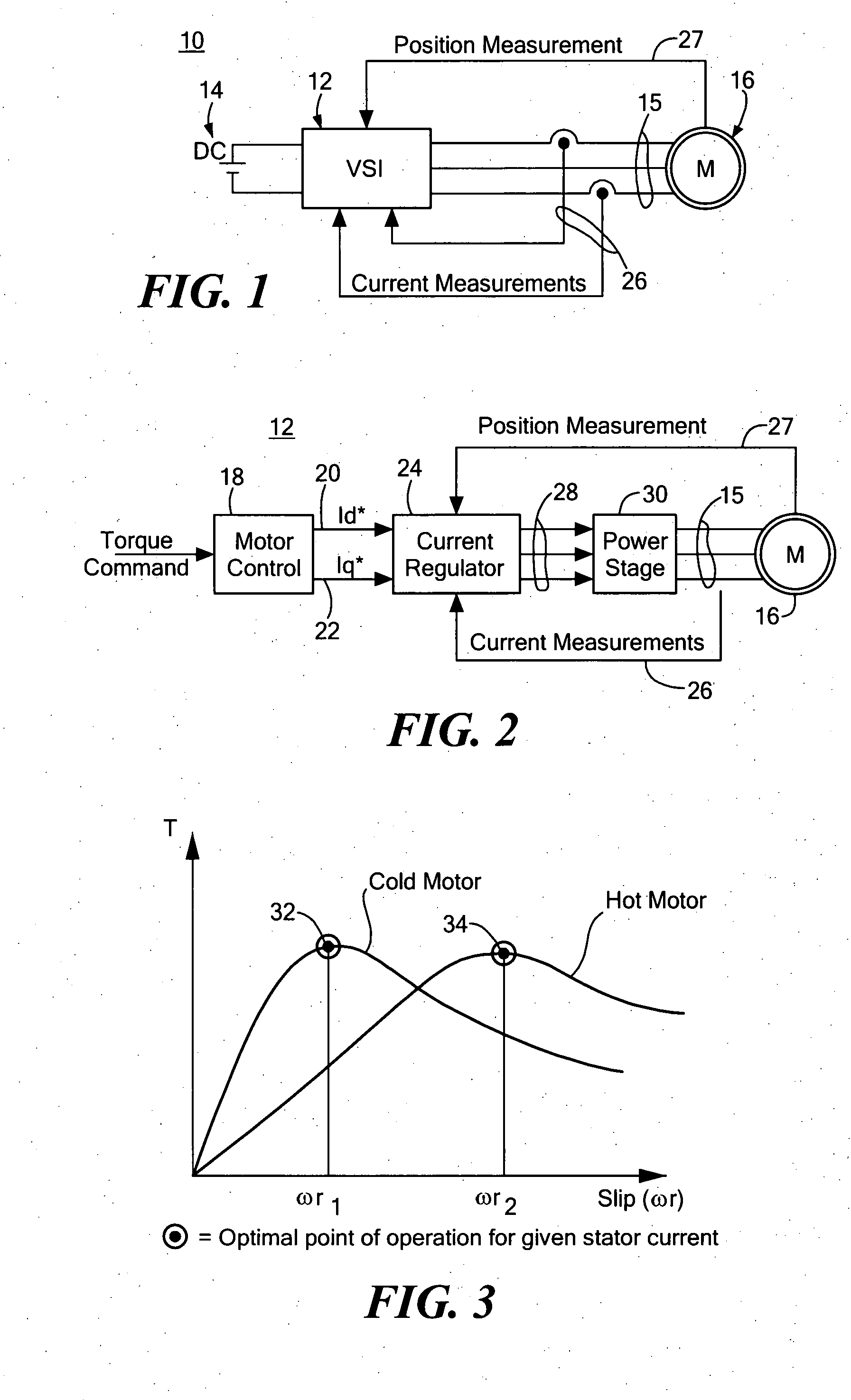
[0041]There is shown in FIG. 1, an AC induction motor control 10 including a voltage source inverter (VSI) 12 which derives power from a dc source, such as battery 14, to drive AC induction motor 16. VSI 12 receives current measurement feedback on line 26 and position measurement feedback on line 27. VSI 12 may include a mo...


PUM


Abstract

Indirect rotor resistance estimation for an AC induction motor is achieved by successively stepping the quadrature command to zero and the direct current command to a predetermined value causing the quadrature stator voltage to decay as a representation of rotor current decay; defining, in response to the decaying stator voltage reaching two spaced thresholds, a voltage/time difference, and retrieving from a storage device the rotor resistance associated with the voltage/time difference.

Description

FIELD OF THE INVENTION[0001]An improved indirect rotor resistance estimator system and method for an AC induction motor.BACKGROUND OF THE INVENTION[0002]Improvements in power-electronics and the advent of digital signal processors (DSPs) has allowed for the use of inexpensive and rugged induction motors in applications which were so far reserved for brushed DC motors (such as traction drives and variable speed industrial drives). By taking advantage of the new control technologies and new hardware available, AC induction motors can achieve the same dynamic performance as a DC motor, while exhibiting higher power density, lower cost and zero maintenance.[0003]The two most prevalent advanced control methods for induction motors are “field oriented control” (FOC) and “direct torque control” (DTC)”. FOC was first proposed over thirty years ago (in 1971 by F. Blaschke), while the more “modern” DTC emerged a decade later. The advantage of DTC is its simplicity, requiring no current regula...

Claims


Application Information

Patent Timeline
IPC IPC(8): G01R27/00G06F19/00
CPCG01R31/343H02P21/145H02P21/085H02P29/0061H02P21/09H02P21/16H02P29/66
Inventor ARNET, BEAT J.
Owner GE HYBRID TECH
Why Eureka
Try Eureka