Dryer fabric and dryer fabric seam area

Inactive Publication Date: 2008-09-25
TAMFELT PMC OY
View PDF34 Cites 5 Cited by
  • Summary
  • Abstract
  • Description
  • Claims
  • Application Information

AI Technical Summary

Benefits of technology

[0008]The invention has an advantage that fasten-off rows need not be separately reinforced by means of silicon or the like, because the fasten-off row of the yarns forming seam loops is at a different location from the fasten-off row of the yarns forming the edge of the seam area. In addition, when one fasten-off row is provided on the borderline between the seam area and the basic fabric, an advantage is achieved that the seam area is quick to weave on the seaming machine. Namely, at the machine direction yarn fastened off on the borderline of the basic fabric there is no need to weave a backside machine direction yarn on the seaming machine in the seam area, and consequently the number of work cycles of the seaming machine is fewer and thus the work is faster to perform.
[0016]The basic idea of an embodiment is that between the top fabric and the bottom fabric there are a plurality of cross machine direction filling yarns and that the filling yarns are arranged in the dryer fabric without interlacing with the yarns of the top fabric and the bottom fabric. The filling yarns may provide additional tenseness to the structure of the dryer fabric. Further, the filling yarns may add to the cross machine direction rigidity of the dryer fabric and may thus render the fabric more stable.
[0018]The basic idea of an embodiment is that the machine direction yarns of the top fabric and the bottom fabric are flat in cross section, for instance, oval or rectangular yarns. As it is known, the flat yarns are rigid in one direction and very flexible in another direction. Hence, the fabric layer woven of flat yarns is very sturdy in fabric plane. The flat yarns support the structure of the fabric in the surface direction thereof. Moreover, when flat yarns are used, the bottom surface may be smoother than in the case of round yarns, and consequently the fabric carries along less air. Thus, the fabric has good aerodynamic properties and good runnability on the paper machine. In addition, the surface facing the web to be dried may be smoother when flat yarns are used than when round yarns are used.

Problems solved by technology

A problem with the conventional dryer fabrics is that it is cumbersome and time consuming to provide seam areas at the dryer fabric ends on the seaming machine.

Method used


Image

  • Dryer fabric and dryer fabric seam area
  • Dryer fabric and dryer fabric seam area
  • Dryer fabric and dryer fabric seam area

Examples


Embodiment Construction

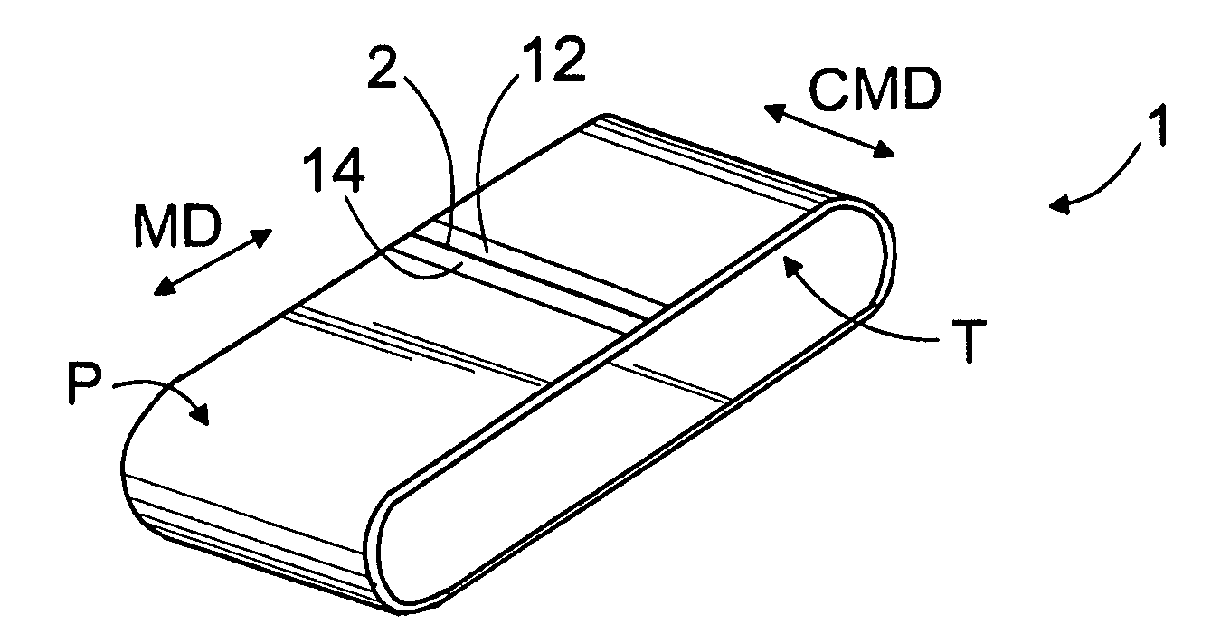
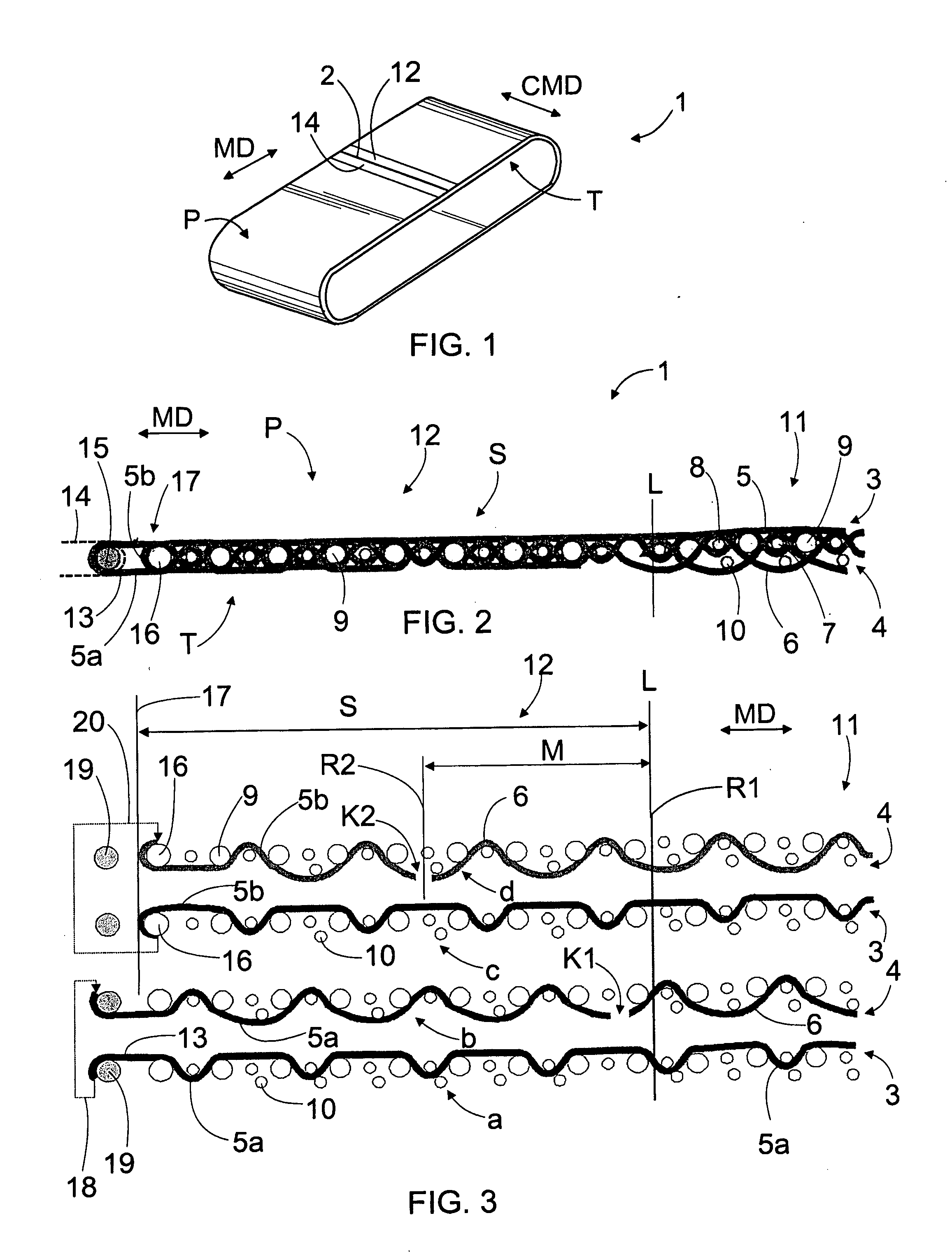
[0027]FIG. 1 shows a greatly simplified view of a dryer fabric 1 that can be run in machine direction MD and that has a width in cross machine direction CMD. The dryer fabric 1 may comprise one or more seams 2 woven separately on the seaming machine, whereby the fabric may be connected to a closed loop in the drying section of a paper machine. The seam makes the mounting of the dryer fabric 1 easier and faster.

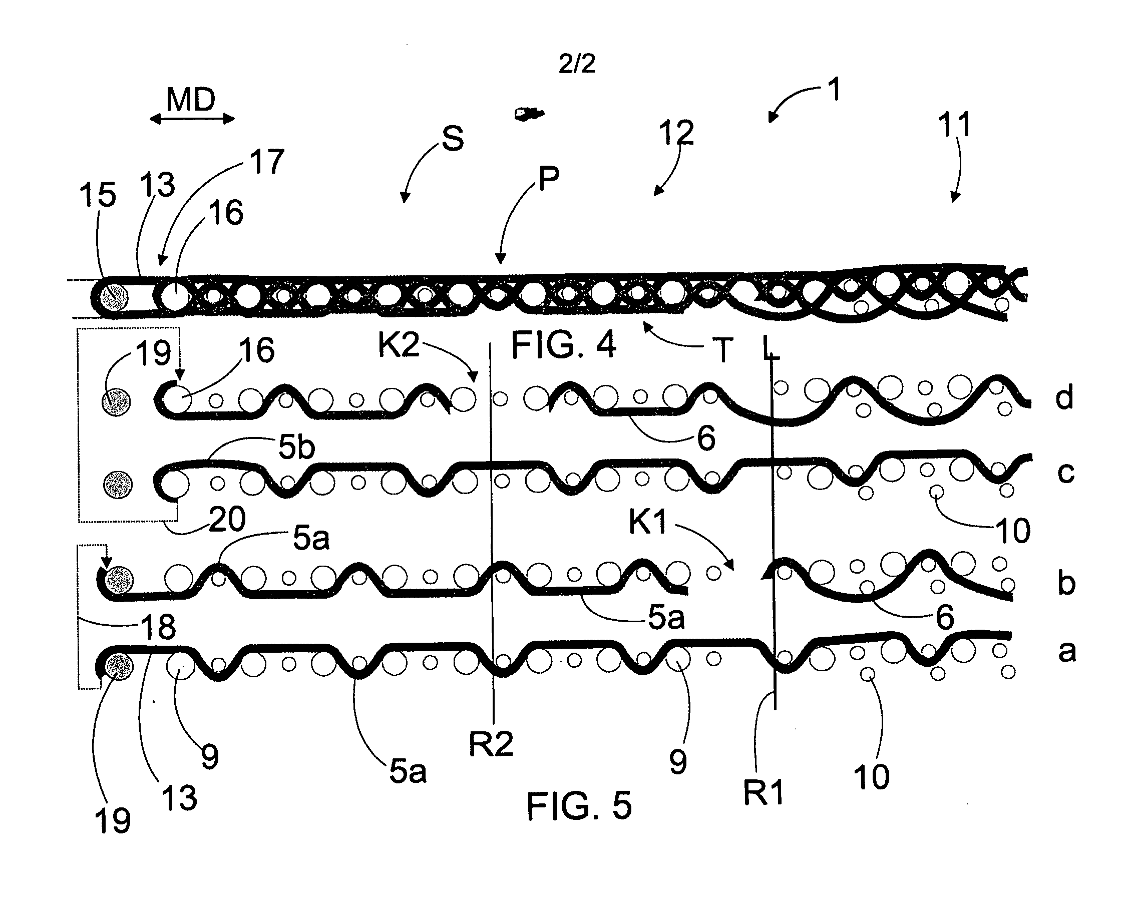
[0028]FIG. 2 shows a dryer fabric 1 of the invention seen in cross machine direction CMD. The dryer fabric 1 has a paper side surface P, against which the paper web to be dried may be arranged in the dryer section. Further, on the opposite side of the dryer fabric there is a bottom surface T, which may be supported against the rolls of the paper machine. The dryer fabric 1 may comprise at least two superposed fabrics, namely a top fabric 3 on the paper side and a bottom fabric 4 on the backside T. The top fabric 3 and the bottom fabric 4 are formed on the weaving machine and t...


PUM

PropertyMeasurementUnit
Structureaaaaaaaaaa
Areaaaaaaaaaaa

Abstract

A dryer fabric and a seam area of a dryer fabric. The basic structure of the dryer fabric comprises at least two superposed machine direction yarn systems. Some yarns of a paper side machine direction yarn system form seam loops at connecting ends and some of the paper side machine direction yarns form an edge of the seam area. All the machine direction yarns of the paper side system make a backward turn at the connecting end and they are fastened off on the backside. The paper side machine direction yarns are cut at a cutting point. Cutting points form a fasten-off row. Yarns that form seam loops are fastened off in a first fasten-off row and yarns that form an edge of the seam area are fastened off in one or more second fasten-off row. One fasten-off row is situated at the beginning line of the seam area.

Description

BACKGROUND OF THE INVENTION[0001]The invention relates to a dryer fabric, which has a bottom surface and a surface facing a paper web to be dried and which is woven of a plurality of machine direction longitudinal yarns and a plurality of cross machine direction transverse yarns; and in which dryer fabric there are at least two superposed machine direction yarn systems, namely, the paper side machine direction yarns and the backside machine direction yarns; and in which dryer fabric there is at least one first cross machine direction connecting end and at least one second cross machine direction connecting end, each of the connecting ends comprising a seam area and on the outermost edge of the connecting end a plurality of seam loops for interconnecting the connecting ends of the dryer fabric and for providing a dryer fabric in the form of a closed loop; and which seam area has a predetermined length in machine direction extending from the seam loops to a cross machine direction lin...

Claims


Application Information

Patent Timeline
IPC IPC(8): D03D1/00D03D15/00D21F1/00D03D25/00D21F7/12D21F7/10
CPCD03D3/04D21F1/0054D03D11/00Y10T428/249922Y10T442/30
Inventor ENQVIST, RAUNO O.LIITOLA, AIRA E.
Owner TAMFELT PMC OY
Why Eureka
Try Eureka