Susceptor
- Summary
- Abstract
- Description
- Claims
- Application Information
AI Technical Summary
Benefits of technology
Problems solved by technology
Method used
Image

Examples
first embodiment
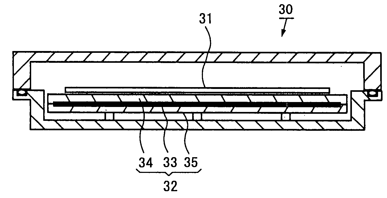
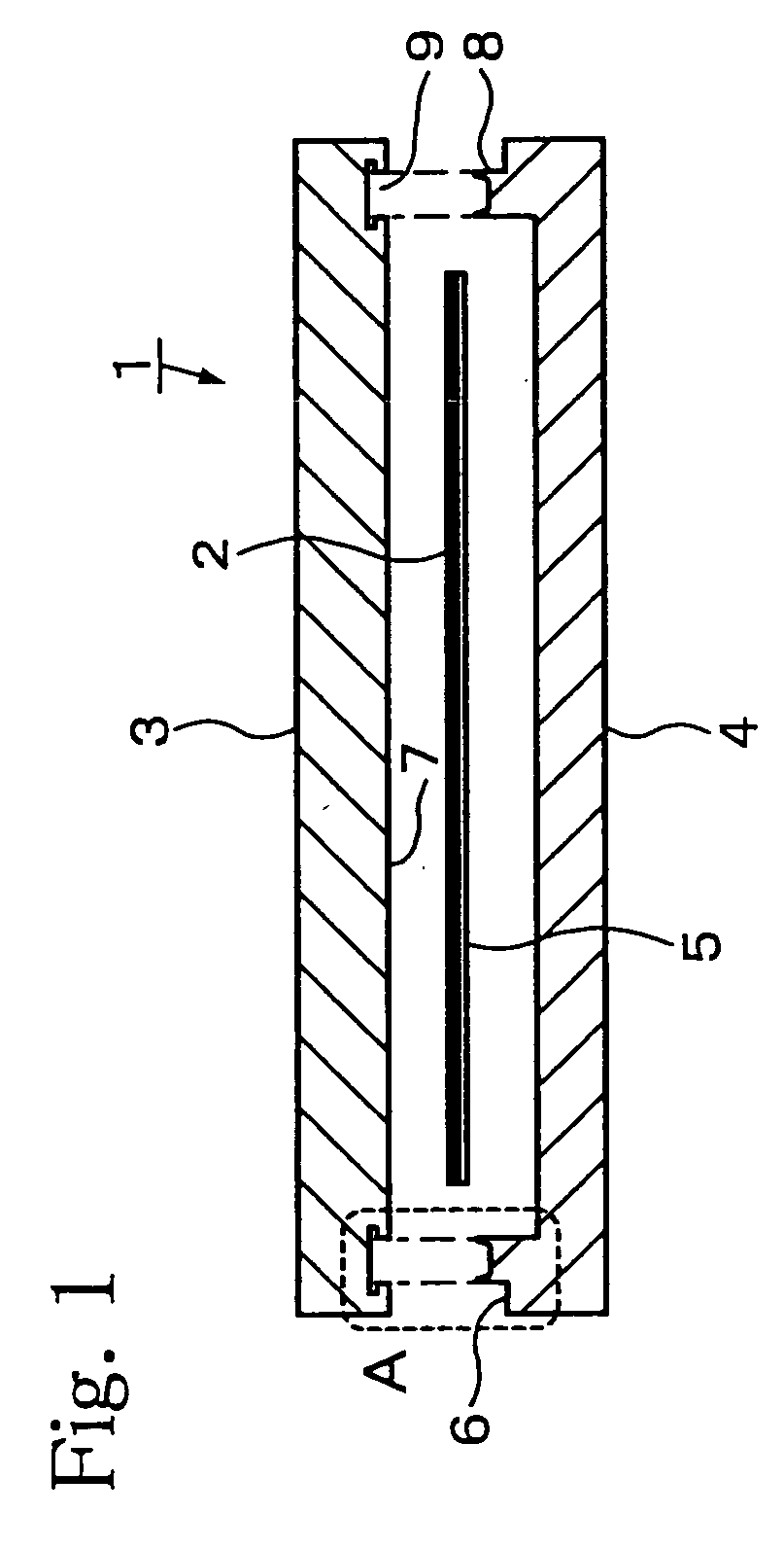
[0043]FIG. 1 shows a structural end view diagram of the susceptor comprising this invention.
[0044]This susceptor [1] is composed of a planar heater [2], which is the substrate heat source, the heater being inserted between and held from above and below by a second plate (specifically, the heat transfer plate [3]) and a first plate (specifically, the retainer plate [4]), and the plates being conjoined at a joining portion A. A metal foil heater or a mica-wrapped heater is used in the planar heater [2], being secured to the joining surface [7] of the heat transfer plate [3] by a thermal shield plate [5] and a screw (not shown in the diagram). Materials having outstanding heat conduction properties, such as aluminum, aluminum alloys, copper, and copper alloys, are used as the materials for the heat transfer plate [3] and the retainer plate [4]. The substrate, being a semiconductor wafer or LCD glass, is mounted directly onto the heat transfer plate [3] or via a plurality of proximity p...
second embodiment
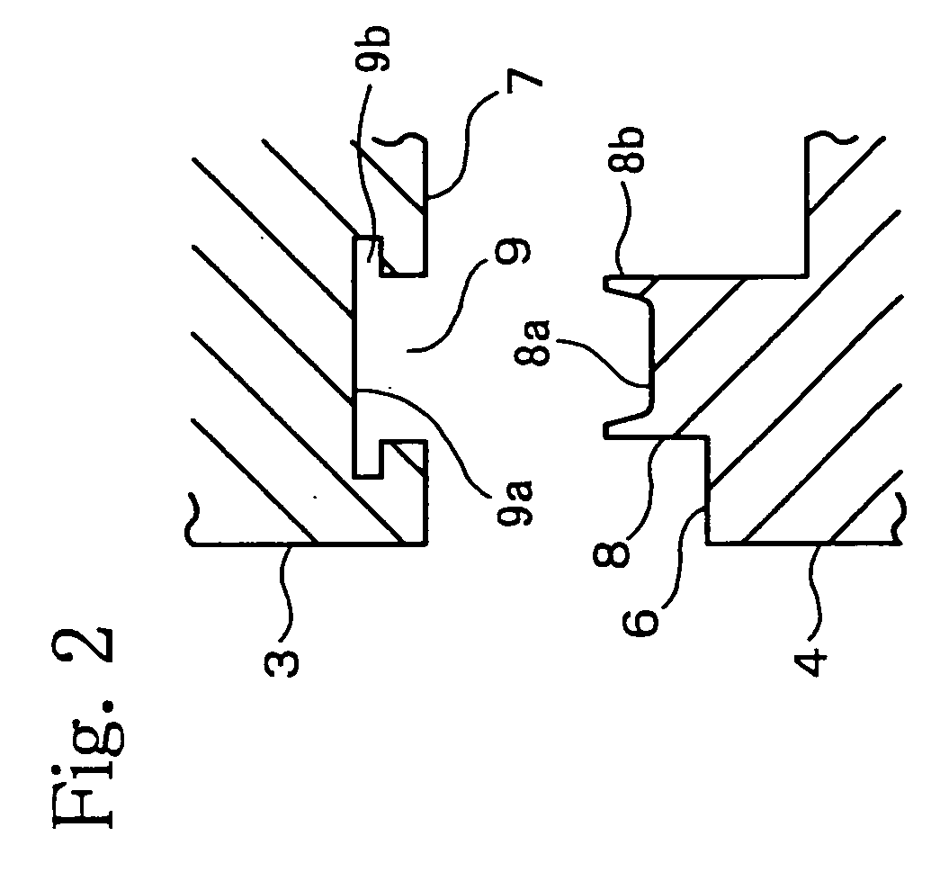
[0051]FIG. 8 shows the joining portion of the susceptor comprising this invention.
[0052]In this embodiment, in addition to the cross-section of the groove part [9] assuming an inverted trapezoidal shape (table-like shape), the height of the wall parts [8b] of the protruding part [8] is increased.
[0053]As shown in FIG. 9, it is preferable to set the dimensions of the width [W1] and the total height [H1] of the protruding part [8], as well as the aperture width [W3] and the total depth [H3] of the groove part [9], such that 60% to 80% of the volume of the groove part [9] after caulking is filled by the protruding part [8]. It is also preferable to set the width [W1] slightly smaller than the apature width [W3]. Doing the above ensures that the joint will be fully and firmly caulked. Furthermore, in order to increase the adhesion between the wall parts [8b] of the protruding part [8] and the slope [9b] of the groove part [9], it is preferable if the angle γ formed by the taper [8c] of ...
third embodiment
[0062]FIG. 20 is a structural end diagram of the susceptor comprising this invention.
[0063]As shown in FIG. 21, in this embodiment, mounting grooves [17] having an approximately semicircular or U-shaped cross-section are formed on the bottom surface of the concave portion [8a] of the protruding part [8] and the bottom surface [9a] of the groove part [9] at the joining portion [B]. The sheath heater [14] (i.e., a substrate heat source) or the pipe [16] (i.e., a substrate heat source or a substrate cooling source), is installed inside these mounting grooves [17]. As shown in FIG. 22, the mounting groove [17] may be formed only on the bottom of the concave portion [8a] of the protruding part [8] or, as shown in FIG. 23, may be formed only on the bottom surface [9a] of the groove part [9]. Furthermore, with regard to the mounting grooves [17] of FIGS. 22 and 23, for the same reasons as above, it is preferable if the depth [H4] of the groove portion that houses the pipe is smaller than t...
PUM
 Abstract
Description
Claims
Application Information
 - Generate Ideas
- Intellectual Property
- Life Sciences
- Materials
- Tech Scout
- Unparalleled Data Quality
- Higher Quality Content
- 60% Fewer Hallucinations
Browse by: Latest US Patents, China's latest patents, Technical Efficacy Thesaurus, Application Domain, Technology Topic, Popular Technical Reports.
© 2025 PatSnap. All rights reserved.Legal|Privacy policy|Modern Slavery Act Transparency Statement|Sitemap|About US| Contact US: help@patsnap.com