
Semiconductor device

a technology of semiconductors and devices, applied in the direction of power conversion systems, dc-dc conversion, instruments, etc., can solve the problems of output voltage oscillation, overshoot or undershoot,

Inactive Publication Date: 2008-09-25
SEIKO INSTR INC
View PDF8 Cites 42 Cited by
  • Summary
  • Abstract
  • Description
  • Claims
  • Application Information

AI Technical Summary

Benefits of technology

The present invention provides a current mode step-down switching regulator with an overvoltage protection circuit. The overvoltage protection circuit can suppress overshoot of output voltage and detect changes in output voltage even if being a current mode step-down switching regulator. This prevents malfunctions such as oscillation of the output voltage. The semiconductor device includes an overvoltage protection circuit, a comparator, and a discharge switch. The overvoltage protection circuit can compare a target voltage with the output voltage and make the output terminal in a discharge state when the output voltage exceeds the target voltage. The semiconductor device also includes a switch for controlling the on / off of a coil and a control circuit for controlling the switch. The overvoltage protection circuit can directly lower the voltage of the output terminal by discharge when the output voltage rises, resulting in stable output voltage to a load without malfunction.

Problems solved by technology

As a result, the overshoot or undershoot is caused.
However, when the load suddenly changes, current whose direction is opposite to the direction of current which normally passes through the current detection circuit 206 passes through the current detection circuit 206, and therefore, in some cases, the current detection circuit 206 cannot correctly detect the current when the current decreases, and thus, a current sense circuit may malfunction to cause, for example, oscillation of the output voltage.

Method used


Image

  • Semiconductor device
  • Semiconductor device
  • Semiconductor device

Examples


Embodiment Construction

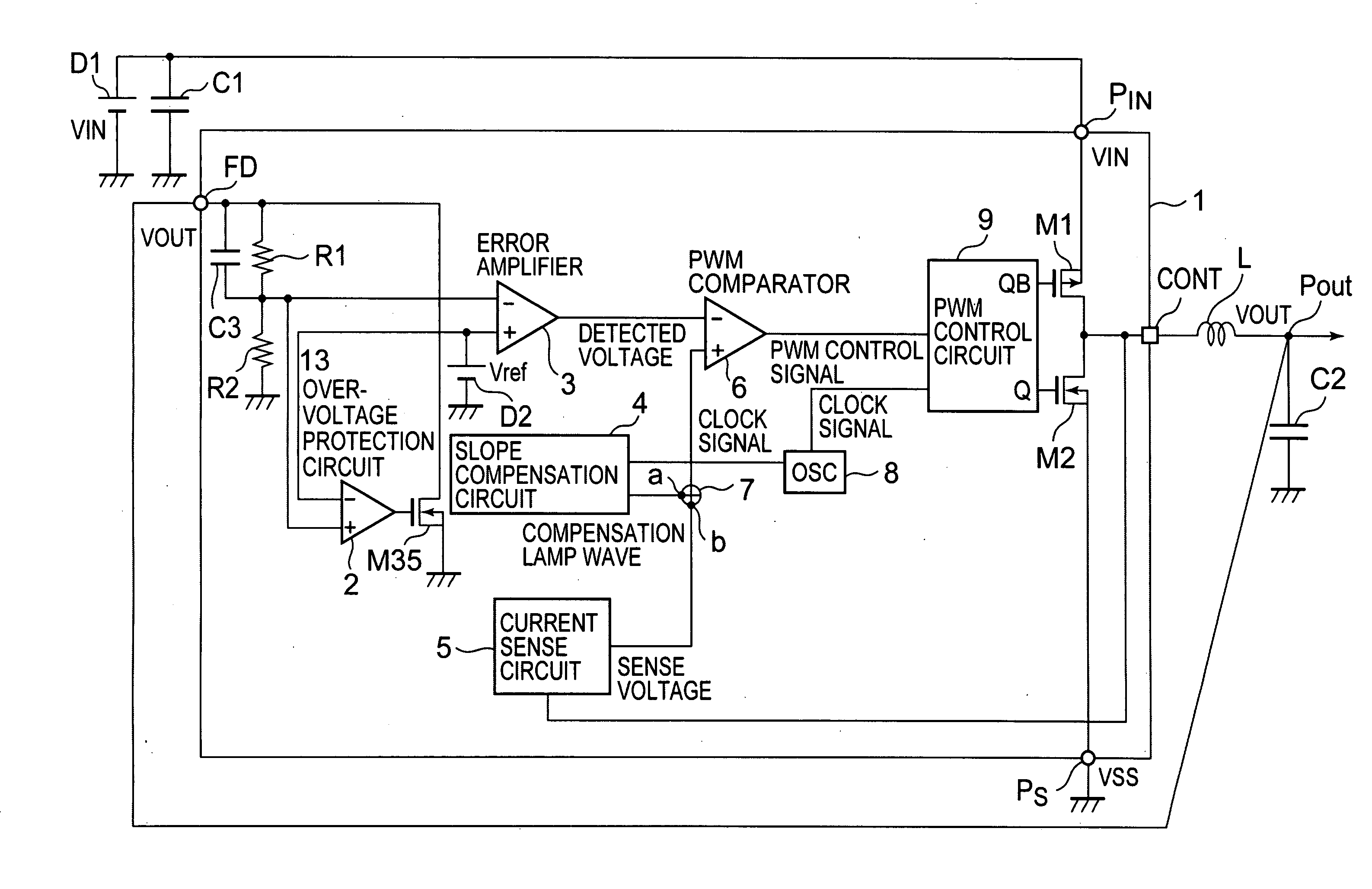
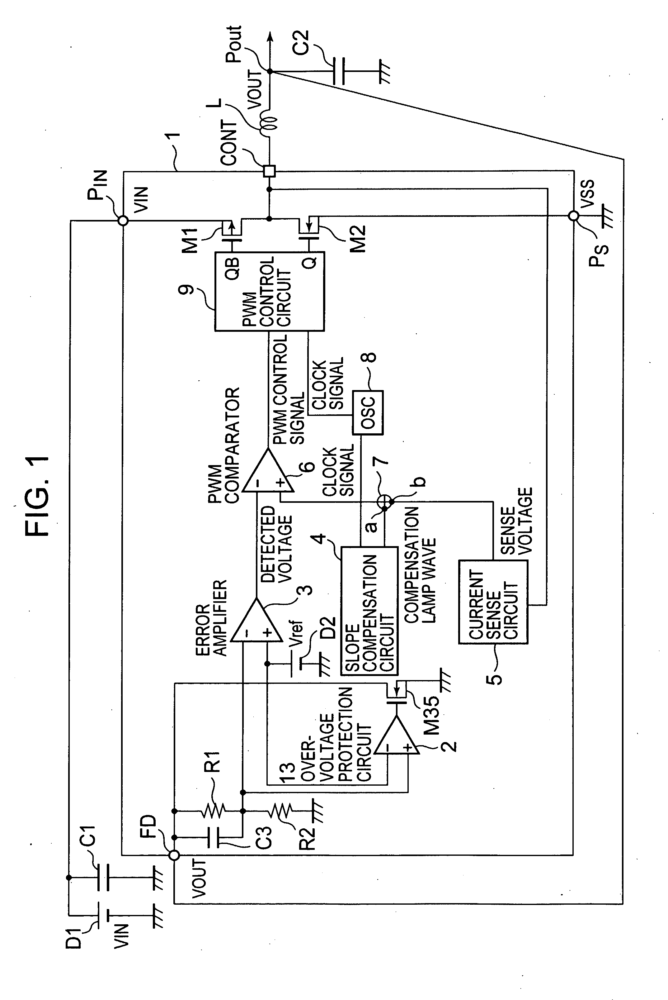
[0030]A semiconductor device 1 for a current mode step-down switching regulator using an overvoltage protection circuit 13 according to an embodiment of the present invention will be described in the following with reference to the drawings. FIG. 1 is a block diagram illustrating an exemplary structure of a step-down switching regulator according to this embodiment. The most distinctive feature of the present invention is the overvoltage protection circuit 13 provided to suppress overshoot of output voltage Vout which is output from an output terminal Pout to the load when a load suddenly decreases, and the detail thereof will be described in the following.

[0031]In FIG. 1, the current mode step-down switching regulator according to this embodiment has the semiconductor device 1 for the current mode step-down switching regulator, a coil L for voltage conversion (in this embodiment, step-down), and a capacitor C2 for smoothing voltage which is output from the coil L. When a P-channel ...


PUM


Abstract

To obtain a switching regulator which, when a load suddenly decreases, suppresses overshoot of output voltage without oscillating the output voltage is provided, even if being a current mode switching regulator, the present invention provides a semiconductor device for a switching regulator for converting input direct current voltage input from a direct current power supply to set direct current output voltage and outputting the output voltage from an output terminal, including: an overvoltage protection circuit for: comparing a target voltage with the output voltage at the output terminal; and making the output terminal in a discharge state when the output voltage exceeds the target voltage.

Description

BACKGROUND OF THE INVENTION [0001]1. Field of the Invention[0002]The present invention relates to a semiconductor device for a current mode switching regulator which controls output voltage using direct current input power supply based on detected values of output voltage and output current.[0003]2. Description of the Related Art[0004]As a current mode step-down switching regulator in which direct current voltage is input from a direct current power supply, and the output direct current voltage is supplied to a load, there is used a circuit as illustrated in FIG. 5 (see, for example, JP 2005-45942 A). The current mode step-down switching regulator illustrated in FIG. 5 has a switch 207, a pulse width control circuit 205, a diode 202, a capacitor 212, a coil 208, a current detection circuit 206, and a voltage detection circuit 204. A voltage Vin which is input from a direct current power supply 201 is stepped down, and the stepped-down output voltage is supplied to a load 209.[0005]I...

Claims


Application Information

Patent Timeline
Patent Type & Authority Applications(United States)
IPC IPC(8): G05F1/575
CPCH02M3/158G11C5/14
Inventor UEHARA, OSAMU
Owner SEIKO INSTR INC
Learn More