Dust Core and Method for Producing Same

a technology of dust core and powder core, which is applied in the field of dust core and method for making the same, can solve the problems of increasing increasing the iron loss in the dust core, and destroying the coating of the dust core, and achieves the effects of superior insulation properties of these materials, efficient restriction of eddy current flow, and high heat resistan

Inactive Publication Date: 2008-09-25
SUMITOMO ELECTRIC IND LTD
View PDF7 Cites 53 Cited by
  • Summary
  • Abstract
  • Description
  • Claims
  • Application Information

AI Technical Summary

Benefits of technology

[0012]The object of the present invention is to overcome these problems and to provide a powder core and method for making the same that is equipped with insulative coating having superior heat resistance, with the coating making it possible to adequately restrict the flow of eddy currents between particles.
[0022]With the present invention as described above, it is possible to provide a powder core and method for making the same that includes an insulative coating with superior heat resistance and that can adequately restrict eddy current flow between particles by efficiently using the coating.

Problems solved by technology

However, when the iron base powder disclosed in Patent Document 1 is compacted, there is significant abrasion between coatings disposed on powder surfaces, resulting in a powder core in which coatings have been destroyed.
This leads to eddy current flowing between the iron base particles, resulting in increased iron loss in the powder core due to eddy current loss.
This prevents the coating from performing adequately as an insulation coating at the thin sections, similarly resulting in increased iron loss in the powder core due to eddy current loss.
As a result, when heat treatment to remove distortions in the powder core is performed, the degradation of the upper layer coating can be limited.

Method used


Image

  • Dust Core and Method for Producing Same
  • Dust Core and Method for Producing Same
  • Dust Core and Method for Producing Same

Examples


examples

[0054]The powder core of the present invention was evaluated using the examples described below.

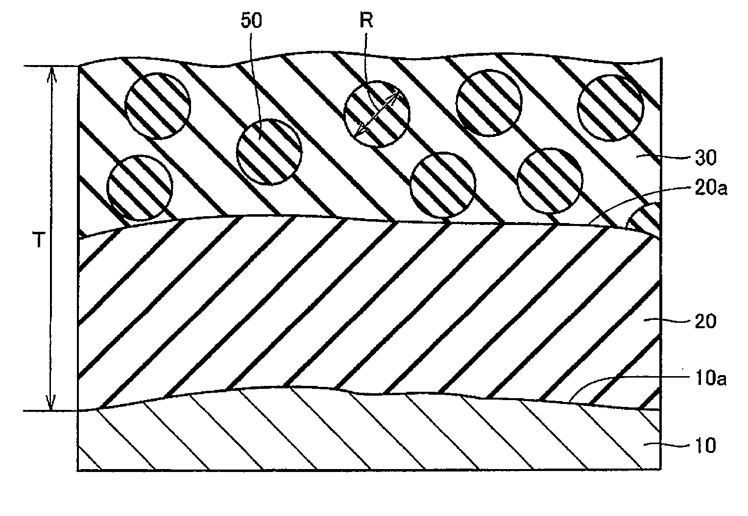
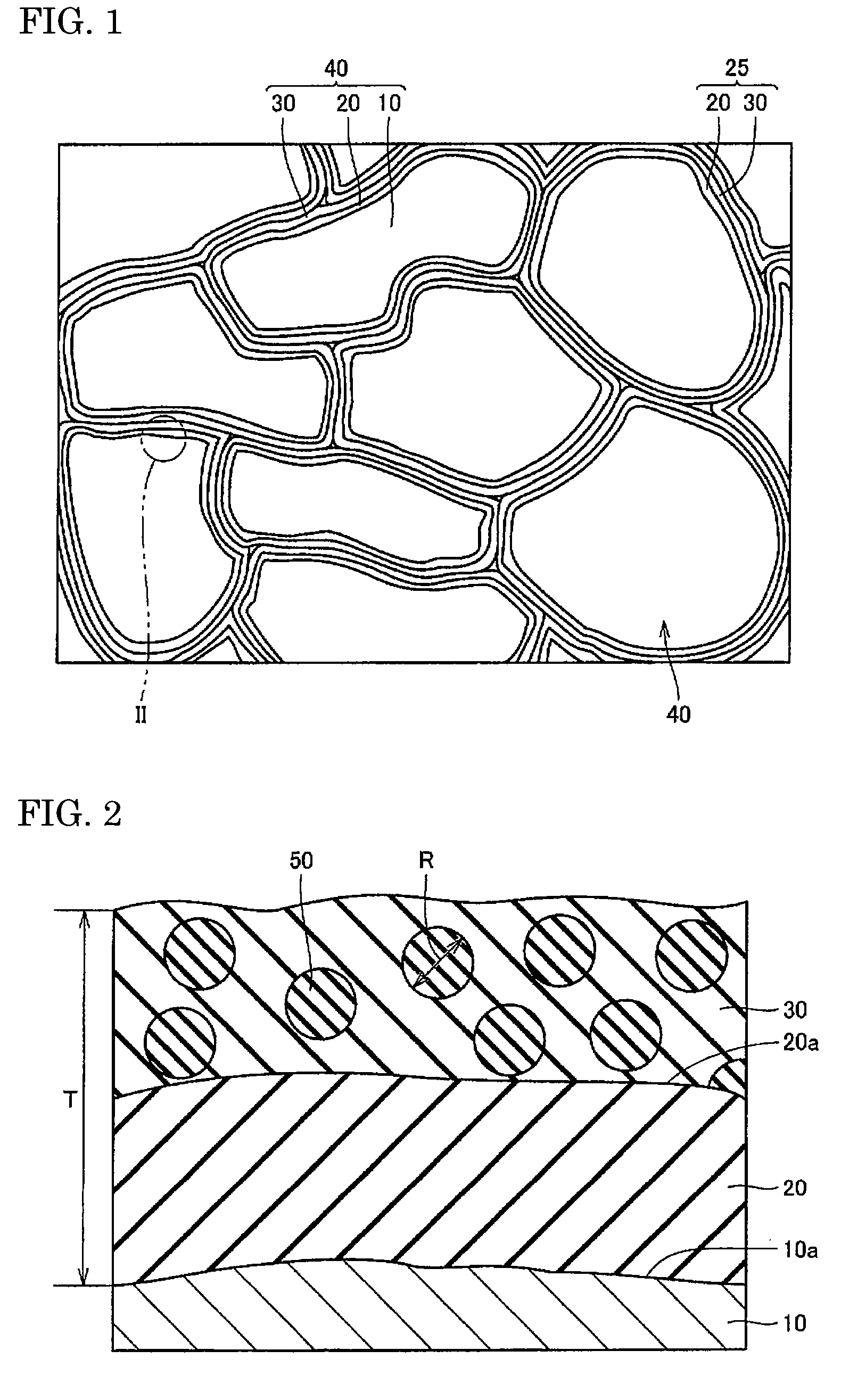
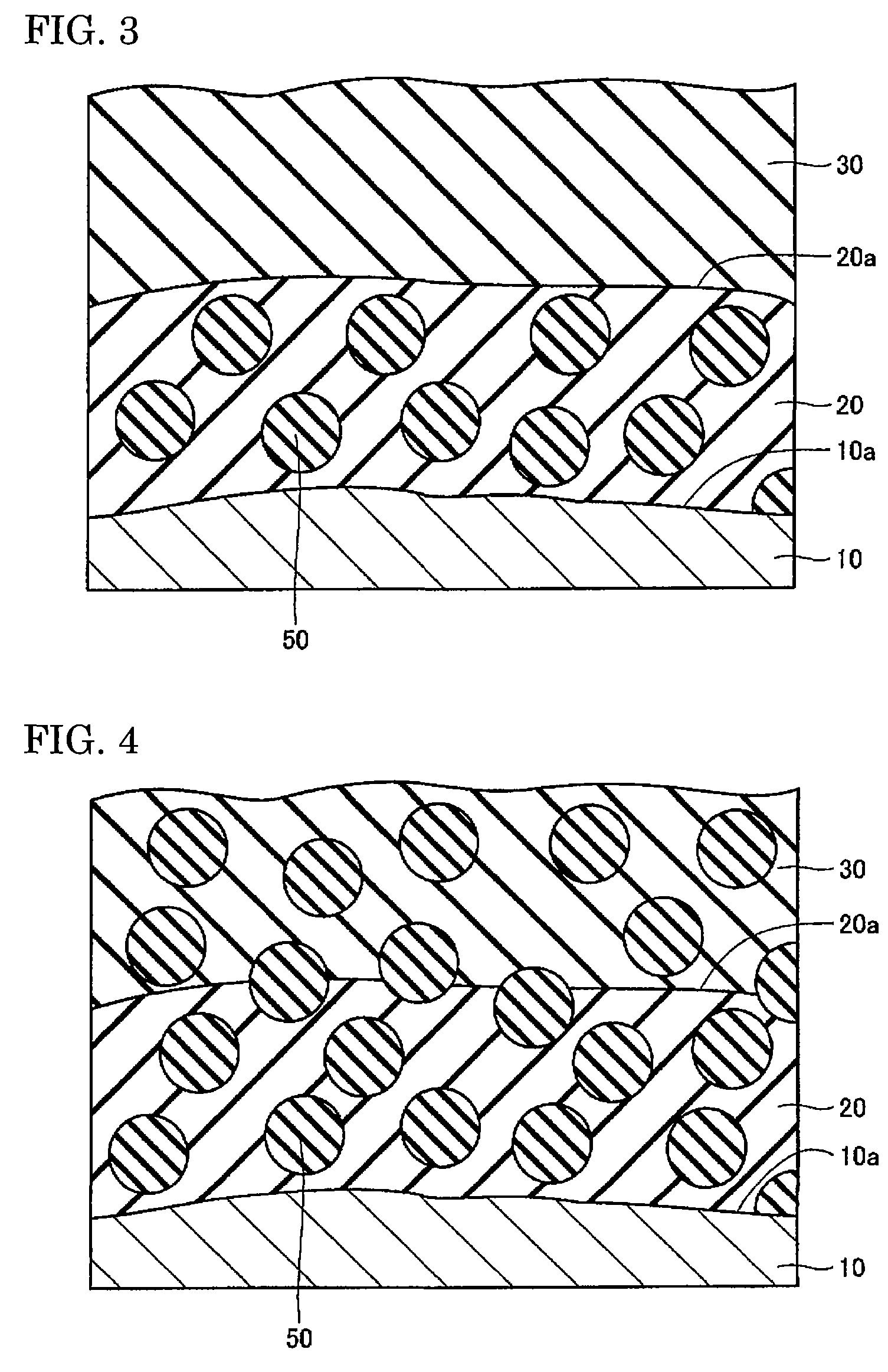
[0055]For the metal magnetic particle 10, the commercially available atomized pure iron powder (product name “ABC100.30”) from Hoganas Corp. was used. This atomized pure iron powder was immersed in a ferric phosphate aqueous solution and stirred to form on the surface of the atomized pure iron powder a ferric phosphate compound coating, serving as the lower layer coating 20. Phosphoric acid compound coatings with average thicknesses of 50 nm and 100 nm were prepared.

[0056]Next, silicone resin (product name “XC96-BO446”) from GE Toshiba Silicone Co., Ltd. and silicon dioxide powder is dissolved and dispersed in ethyl alcohol, and the coated atomized pure iron powder described above was deposited in the solution. The silicone resin was dissolved so that it was 0.25 percent by mass relative to the atomized pure iron powder and the silicon dioxide powder was dissolved so that it was 0.02 perc...


PUM

PropertyMeasurementUnit
thicknessaaaaaaaaaa
thicknessaaaaaaaaaa
temperatureaaaaaaaaaa

Abstract

The object of the present invention is to provide a powder core and method for making the same that is equipped with insulative coating having superior heat resistance, with the coating making it possible to adequately restrict the flow of eddy currents between particles.The powder core is equipped with a plurality of compound magnetic particles bonded to each other. Each of said plurality of composite magnetic particles includes: a metal magnetic particle 10; an insulative lower layer coating 20 surrounding a surface 10a of said metal magnetic particle 10; an upper layer coating 30 surrounding said lower layer coating 20 and containing silicon; and dispersed particles 50 containing a metal oxide compound and disposed in said lower layer coating 20 and / or said upper layer coating 30. A mean particle diameter R of the dispersed particles 50 meets the condition 10 nm<R≦2 T, where the average thickness of the coating combining the lower layer coating 20 and the upper layer coating 30 is T.

Description

TECHNICAL FIELD[0001]The present invention relates generally to a powder core and method for making the same. More specifically, the present invention relates to a powder core used in motor cores, reactors for power supply circuits, and the like, and a method for making the same.BACKGROUND ART[0002]In recent years, there has been a strong demand for compact designs, high efficiency, and high output for electrical devices equipped with an electromagnetic valve, a motor, or a power supply circuit. With these electrical devices, using high frequencies as the operating frequency range is effective. Thus, higher frequencies are being used more and more, e.g., from hundreds of Hz to several kHz for electromagnetic valves, motors, and the like, and from tens of kHz to hundreds of kHz for power supply circuits.[0003]Electrical devices such as electromagnetic valves and motors have been operated primarily with frequencies of no more than hundreds of Hz, and used so-called electromagnetic ste...

Claims


Application Information

Patent Timeline
Patent Type & Authority Applications(United States)
IPC IPC(8): H01F27/255H01F1/24H01F41/02H01F1/33
CPCH01F1/24H01F1/33H01F3/08H01F41/0246Y10T428/2996Y10T428/2993Y10T29/4902Y10T428/2991Y10T428/2995
Inventor KUGAI, HIROKAZUIGARASHI, NAOTOMAEDA, TORUHIROSE, KAZUHIROTOYODA, HARUHISAMIMURA, KOJINISHIOKA, TAKAO
Owner SUMITOMO ELECTRIC IND LTD
Why Eureka
Try Eureka