Hearth plate including side walls defining a processing volume

a technology of hearth plate and processing volume, which is applied in the direction of muffle furnace, furnace floor, furnace, etc., can solve the problems of reducing the amount of space in the furnace for holding materials to be processed, gas may not be heated and mixed to an adequate degree before entering the furnace, and affecting the effect of heat dissipation

Inactive Publication Date: 2008-09-25
HONEYWELL INT INC
View PDF20 Cites 3 Cited by
  • Summary
  • Abstract
  • Description
  • Claims
  • Application Information

AI Technical Summary

Problems solved by technology

Conventional gas preheating systems generally occupy a relatively large part of the lower portion of a furnace, and this reduces the amount of space in the furnace for holding materials to be processed.
If the thickness of such conventional preheaters is reduced, gases may not be heated and mixed to an adequate degree before entering the furnace.
The thickness of the preheating system therefore represents a tradeoff between the amount of usable space inside the furnace taken up by the system and the ability of the preheating system to adequately preheat and distribute the gas before it is released into the furnace.
When the products being processed in such a furnace are treated with a hydrocarbon containing gas, the hydrocarbon gas can leave harmful deposits on the resistance heating elements.
This shielding gas, however, tends to dilute the hydrocarbon containing processing gas used to treat the products in the furnace, and this tends to increase the processing time and potentially decrease the quality of a final product.
However, stacking products on a hearth plate and then placing a cylindrical tube over each stack of products it time consuming and labor intensive and reduces the furnace volume available for holding products.

Method used


Image

  • Hearth plate including side walls defining a processing volume
  • Hearth plate including side walls defining a processing volume
  • Hearth plate including side walls defining a processing volume

Examples


Embodiment Construction

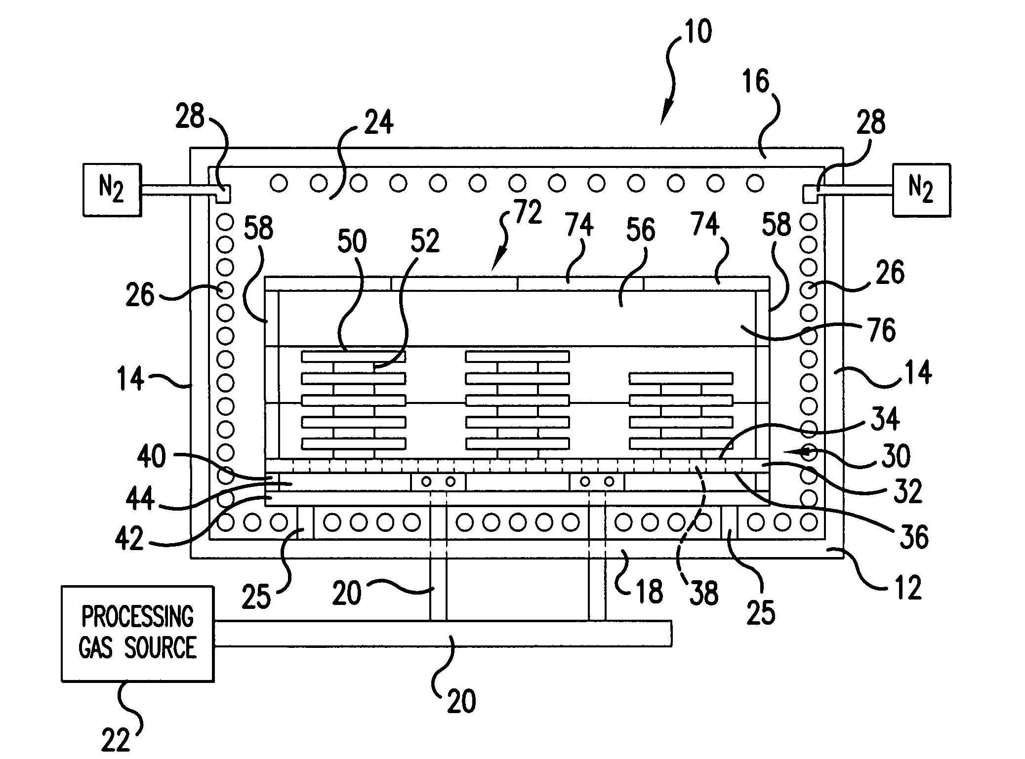
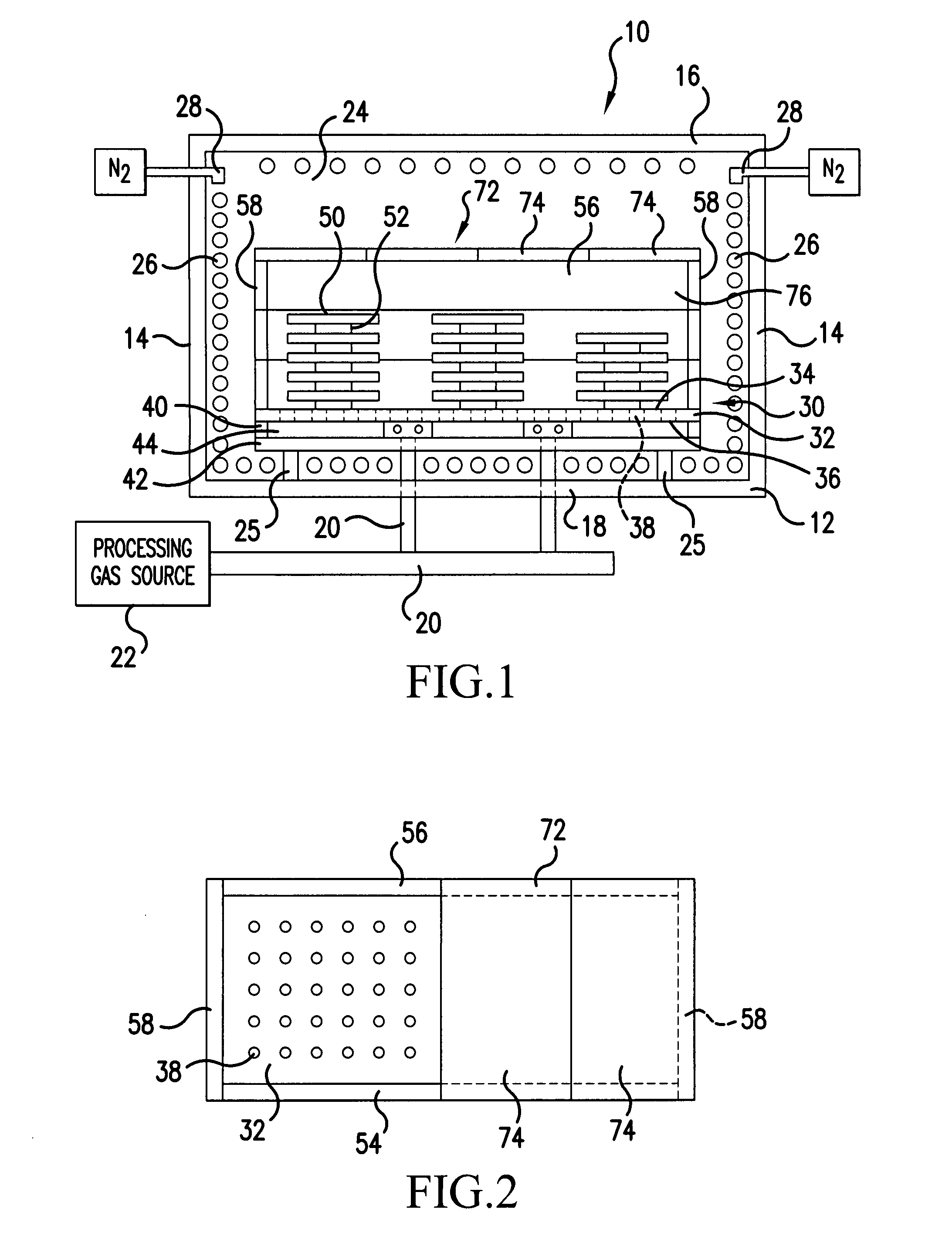
[0013]Referring now to the drawings, wherein the showings are for purposes of illustrating embodiments of the invention only and not for the purpose of limiting same, FIG. 1 illustrates a furnace 10 having a floor 12, side walls 14 and a top 16. Floor 12 includes openings 18 to which processing gas pipes 20 are connected providing processing gas from a gas source 22 to the interior 24 of the furnace 10. Resistance heating elements 26 are mounted on the floor 12, side walls 14 and top 16 of furnace 10 and connected to a source of current (not shown) for heating the interior 24 of the furnace 10 in a well known manner. Shielding gas nozzles 28 are mounted near the resistance heating elements 26 and provide a shielding flow of nitrogen or other suitable gas over the resistance heating elements at a positive pressure to substantially prevent processing gases from contacting the heating elements. A conventional venting system (not shown) is provided for removing the nitrogen and processi...


PUM

PropertyMeasurementUnit
interior volumeaaaaaaaaaa
volumeaaaaaaaaaa
resistanceaaaaaaaaaa

Abstract

A hearth plate (30) includes a flat rectangular plate (32) having a top surface (34), a bottom surface (36), and a plurality of through openings (38) between the top surface (34) and bottom surface (36), four support walls (40) having top edges connected around the periphery of the bottom surface (36) and bottom edges and a bottom wall (42) connected to the bottom edges of the support walls (40). A preheater structure (46) is mounted in the space (44) defined by the four support walls (40), flat rectangular plate (32) and bottom wall (42), and a rectangular enclosure comprising four interconnected graphite walls (54, 56, 58) is mounted around the peripheral edge of the top surface (34) to define a processing volume for receiving objects (50) to be processed. A graphite lid (72) is removably supported by the rectangular enclosure.

Description

FIELD OF THE INVENTION[0001]The present invention is directed to an improved hearth plate structure for supporting a product in a furnace, and, more specifically, toward an improved hearth plate that includes a plurality of side walls and a lid defining with the side walls a processing volume for holding products to be processed in a furnace.BACKGROUND OF THE INVENTION[0002]Furnaces for carrying out chemical vapor deposition (CVD) and / or chemical vapor infiltration (CVI) are well known and are discussed for example, in U.S. Pat. No. 6,162,298 to Rudolph, the entire contents of which is hereby incorporated by reference. In such furnaces, process gas is introduced into a lower portion of a furnace where it passes through a gas preheating system. There it is heated and distributed before it enters the processing portion of the furnace.[0003]Conventional gas preheating systems generally occupy a relatively large part of the lower portion of a furnace, and this reduces the amount of spac...

Claims


Application Information

Patent Timeline
Patent Type & Authority Applications(United States)
IPC IPC(8): F27D1/00
CPCC23C16/045F27D1/0043F27B5/04C23C16/452
Inventor MILLER, BRIAN J.WAGHRAY, AKSHAY
Owner HONEYWELL INT INC
Why Eureka
Try Eureka