Turbomachine and method for assembly thereof using a split housing design

a split housing and turbomachine technology, applied in the direction of machines/engines, stators, liquid fuel engines, etc., can solve the problems of high engineering, production and assembly costs, high cost, and high cost, and achieve the effect of improving the operation and efficiency of the turbomachine and facilitating the manufacturing and assembly process

Inactive Publication Date: 2008-09-25
R & D DYNAMICS
View PDF35 Cites 35 Cited by
  • Summary
  • Abstract
  • Description
  • Claims
  • Application Information

AI Technical Summary

Benefits of technology

[0012]The present invention provides a low-cost, split housing design for turbomachinery, such as a blower or a compressor. Such a split housing design also facilitates the manufacturing and assembly process for turbomachines, including machines utilizing foil gas bearing technology to improve operation and efficiency of the turbomachine.

Problems solved by technology

Turbomachines are high technology machines that typically involve high engineering, production and assembly costs in order to achieve and maintain desired levels of performance and efficiency with reduced repair and safety concerns.
Such high costs are typically due to complex design issues and lengthy assembly procedures.
Attempts are frequently made, with little success, to reduce such costs without affecting performance, operation, or efficiency, and without compromising product safety.
Use of foil gas bearing supported turbomachines in high volume commercial products, while providing the advantages identified above, has been limited in application due to high production costs, predominantly driven by expenses associated with manufacture, assembly and testing of the components of the machines.
The complexity of the machines, due to the use of foil gas bearing technology, also adds to such high production costs.
Such turbomachines are extremely sensitive to tolerances, and hence most of the assembly process is manual and requires high tolerance parts.
This process results in excess assembly costs and increased manufacture time.
However, due to repeated handling of the components during this multi-step process, there is an increased risk that some errors may be made between initial balancing and final installation, ultimately leading to poor operation of the machine.
However, accessing the interior cavity in this manner introduces problems, particularly with assembling the rotating assembly in the machine housing.
Any displacement, even if slight, will result in failure of the shaft.
As with the journal bearing assembly, any improper alignment of the thrust bearing assembly with respect to the shaft will result in premature failure of the shaft.
Due to such high tolerance-driven manufacture and assembly procedures of foil gas bearing supported high-speed turbomachines, the cost of production is high and the time for assembly can be lengthy.
Commercial products, such as blowers and compressors, which could greatly make use of high-speed foil gas bearing technology, have not previously done so due to such high production costs, and the associated requirement for repeated manual involvement throughout the assembly process.

Method used


Image

  • Turbomachine and method for assembly thereof using a split housing design
  • Turbomachine and method for assembly thereof using a split housing design
  • Turbomachine and method for assembly thereof using a split housing design

Examples


Embodiment Construction

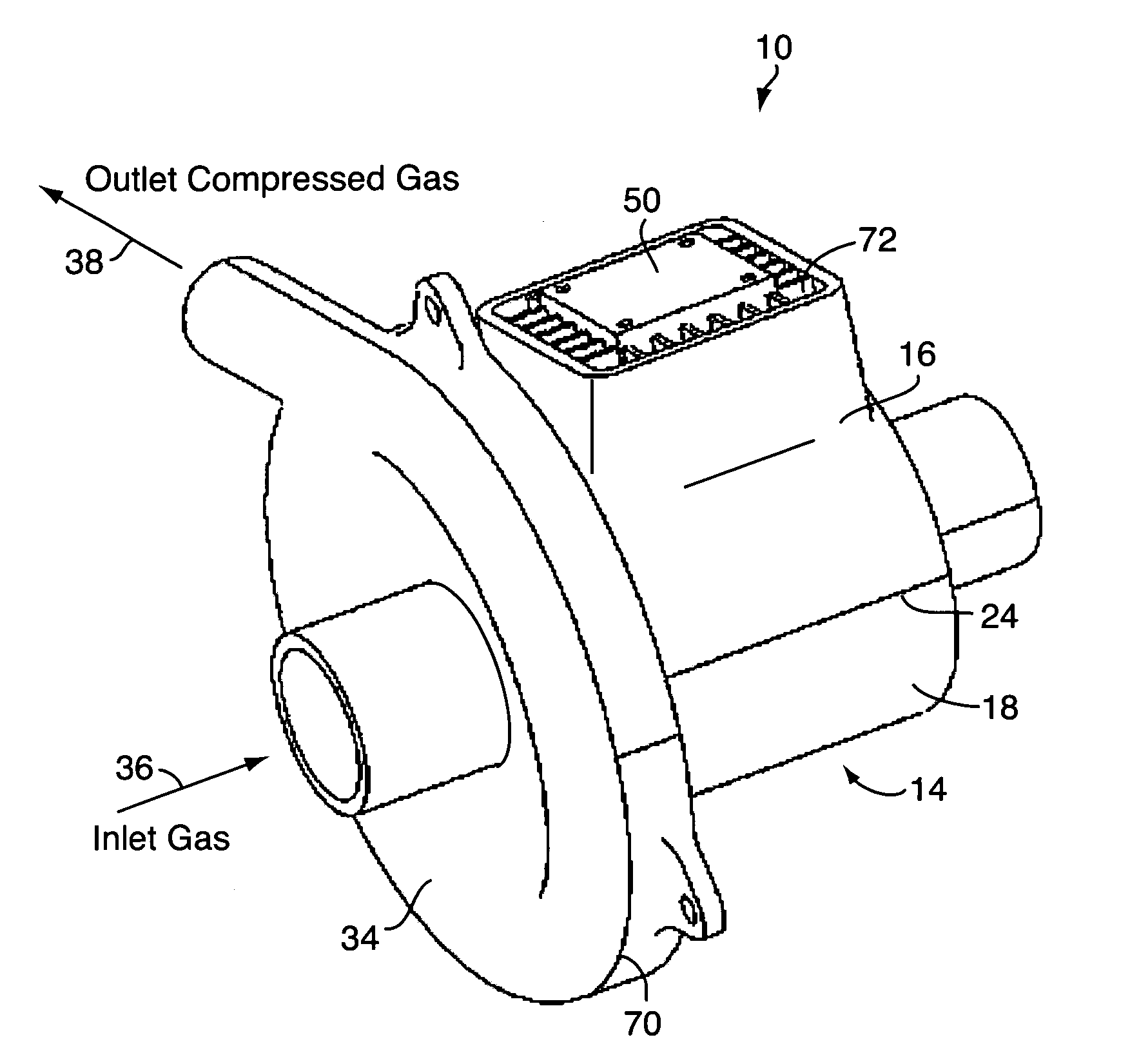
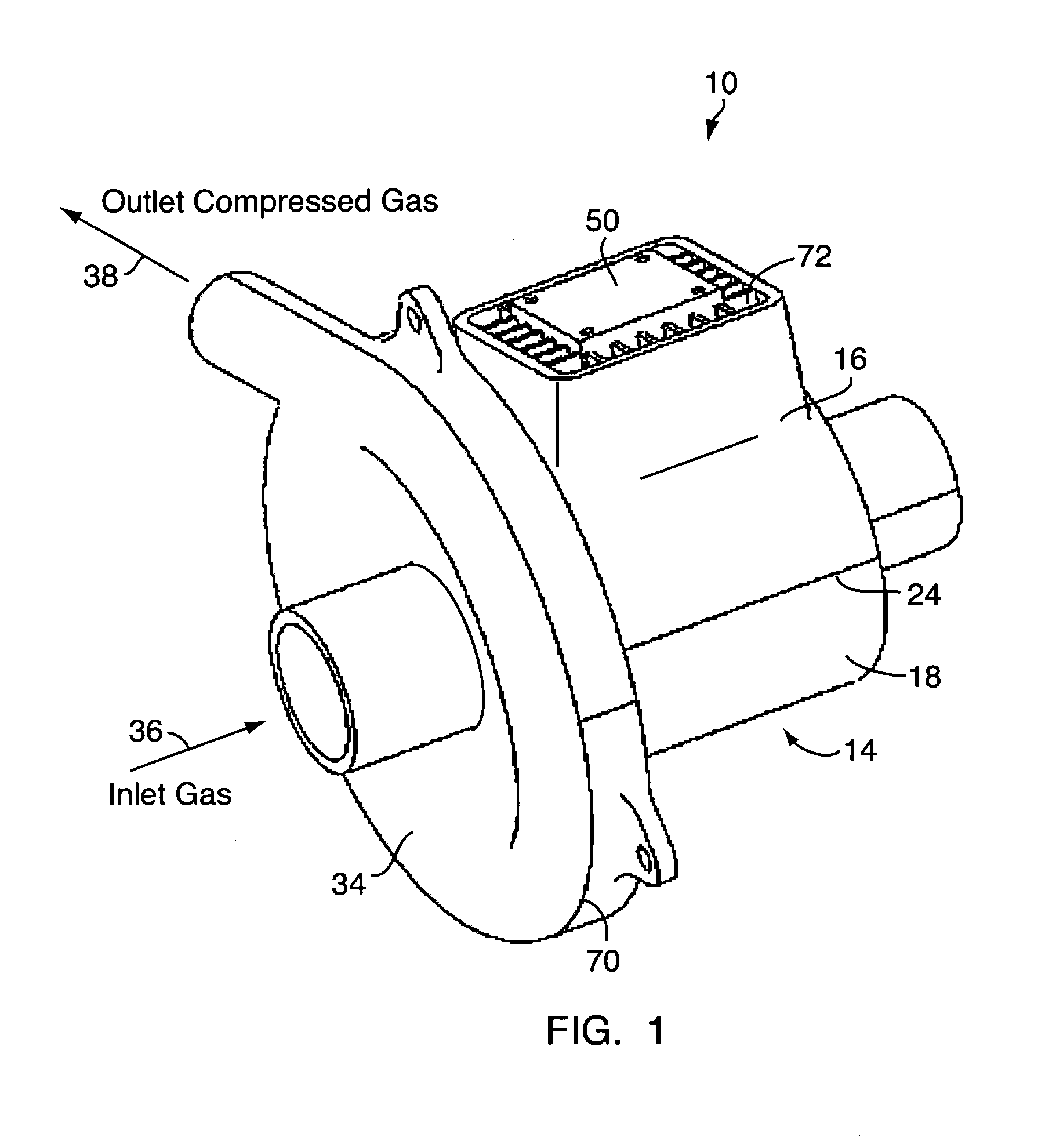
[0026]A turbomachine in accordance with the present invention is illustrated in FIGS. 1-5. As shown and described hereinafter, the illustrated turbomachine is a blower, generally designated by reference numeral 10. Though illustrated as blower 10, the present invention has application in all types of turbomachinery know to the person of ordinary skill in the art, such as compressors, generators, turboalternators, and the like. In general, the present invention provides a low-cost, easy to assemble split housing design for turbomachines that facilitates installation and balancing of a rotating assembly disposed within the housing of the turbomachine.

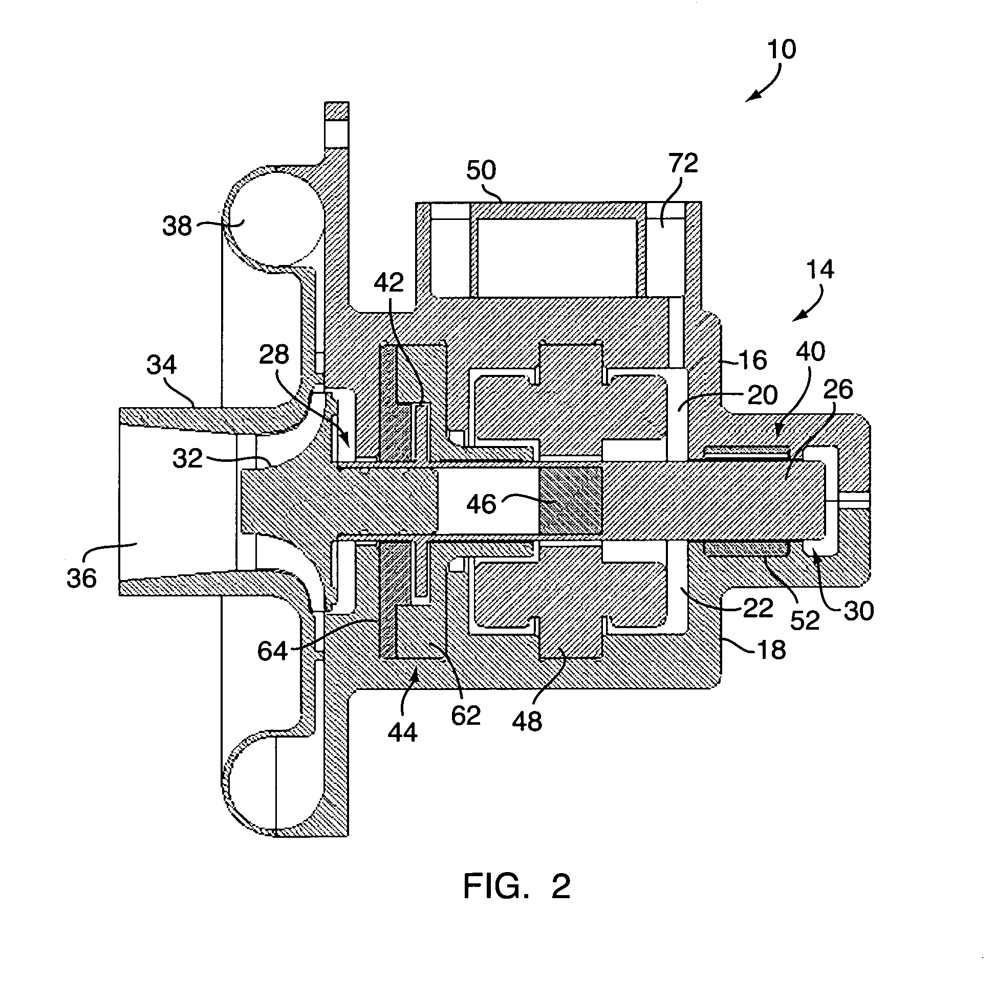
[0027]FIG. 1 generally shows a perspective view of an assembled blower 10 incorporating the design concepts of the present invention. FIG. 2 shows a cross-sectional view of the blower 10 of FIG. 1, and provides an illustration of the internal operative components of the blower 10 essentially forming a rotating assembly, described in more ...


PUM

PropertyMeasurementUnit
shapeaaaaaaaaaa
axis of rotationaaaaaaaaaa
rotationaaaaaaaaaa

Abstract

The present invention provides an improved design for turbomachinery, such as blowers and compressors, for providing pressurized process gas. The improved design comprises two housing portions that fit together to form an interior cavity in which a preassembled rotating assembly may be installed and balanced. Each housing portion includes an interior compartment designed and shaped to correspond to desired positions of components of the rotating assembly. After the preassembled rotating assembly is seated within the interior compartment of the lower housing portion and balanced, the upper housing portion can be fitted to the lower housing portion to complete the machine housing and encompass and hold the rotating assembly in place without the need to remove or disassemble the rotating assembly. A collector cover can thereafter be attached to the assembled machine housing to enclose an impeller operatively mounted on a rotating shaft of the rotating assembly.

Description

CROSS-REFERENCE TO RELATED APPLICATION[0001]This application claims the benefit of U.S. Provisional Application No. 60 / 919,033, filed Mar. 20, 2007, which is incorporated herein by reference.FIELD OF THE INVENTION[0002]The field of the present invention generally pertains to the conception, design and manufacture of turbomachinery, such as blowers and compressors, and associated technologies integrating such devices, and more particularly to a split housing design for such turbomachinery that facilitates manufacture and assembly of such devices without compromising performance.BACKGROUND OF THE INVENTION[0003]Historically, compressed or pressurized gas has been generated by positive displacement machines and turbomachines, such as, blowers and compressors. Turbomachines are high technology machines that typically involve high engineering, production and assembly costs in order to achieve and maintain desired levels of performance and efficiency with reduced repair and safety concern...

Claims


Application Information

Patent Timeline
Patent Type & Authority Applications(United States)
IPC IPC(8): F01D25/24F01D25/16B23P15/04
CPCF04D25/082F04D29/4206Y10T29/49236F05B2220/40F05B2220/706F04D29/626F04D29/5806
Inventor AGRAWAL, GIRIDHARI L.BUCKLEY, CHARLES WILLIAMRAJENDRAN, MUTHUSAMY
Owner R & D DYNAMICS
Why Eureka
Try Eureka