Outboard motor

a technology for outboard motors and motors, applied in marine propulsion, vessel construction, gearing, etc., can solve the problems of large installation space, limited torque increase, complicated structure of outboard motors, etc., and achieve the effect of simple structur

Active Publication Date: 2008-09-25
YAMAHA MOTOR CO LTD
View PDF9 Cites 36 Cited by
  • Summary
  • Abstract
  • Description
  • Claims
  • Application Information

AI Technical Summary

Benefits of technology

[0015]Accordingly, there is a need in the art for an outboard motor which has a small-sized transmission ratio changing unit and is simple in structure.
[0021]In yet another preferred embodiment, the transmission ratio changing unit has a second planetary gear train disposed below the first planetary gear train and including a second sun gear, second double planetary gears, and a second internal gear. The second double planetary gears are connected to the first gear train output, and the second sun gear is connected to a second gear train output that is configured to communicate rotation to the propeller. The second internal gear is connected to a stationary portion via a reverse clutch, and the second double planetary gears are connected by a forward clutch to at least one of the second internal gear and the second sun gear. When the forward clutch is engaged with the reverse clutch disengaged, the second sun gear, the second double planetary gears, and the second internal gear rotate together to cause the first planetary gears of the first planetary gear train and the second sun gear of the second planetary gear train to rotate in the same direction at the same speed to establish a forward drive state. When the forward clutch and the reverse clutch are disengaged, each of the second sun gear, the second double planetary gears, and the second internal gear rotate freely so that the second gear train output at the second sun gear is substantially zero to establish a neutral state. When the forward clutch is disengaged with the reverse clutch engaged, the second internal gear is brought into a fixed state and the second double planetary gears and the second sun gear rotate to cause the first planetary gears of the first planetary gear train and the second sun gear of the second planetary gear train to rotate in opposite directions so as to establish a reverse state.

Problems solved by technology

Such conventional outboard motors, however, have complicated structures, and a large installation space is required since the transmission ratio changing unit has first and second planetary gear trains with one arranged above the other.
However, since there is a limit to the amount by which the torque can be increased and since there is naturally a response time lag between an operation to increase the output and an actual increase in the engine output, the feature of a contra-rotating propeller system cannot be fully exploited.
In addition, such a means tends to lower the traveling mileage.
This method, however, produces a result in which the high water catching ability of the contra-rotating propeller system is not fully exploited.
However, a propeller with a higher pitch requires a larger propeller driving torque at the time of acceleration, and great improvement of the traveling performance by increasing the propeller pitch cannot be expected when a low-speed torque improving means such as a turbo charger as mentioned before is used.

Method used


Image

  • Outboard motor
  • Outboard motor
  • Outboard motor

Examples


Embodiment Construction

[0046]Description is hereinafter made of preferred embodiments of an outboard motor. It is to be understood, however, that the present invention is not limited to the preferred embodiments discussed herein.

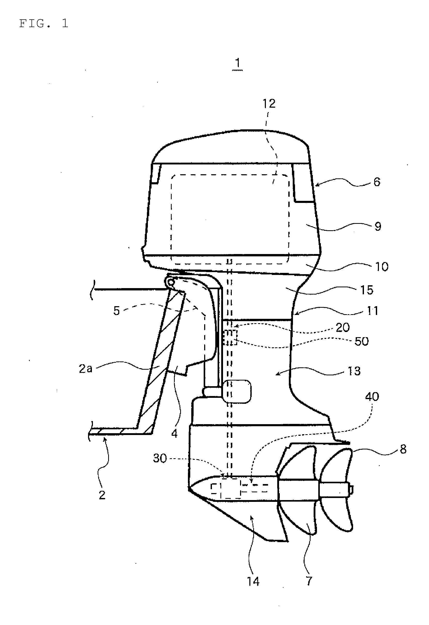
[0047]FIG. 1 through FIG. 7B illustrate a first preferred embodiment.

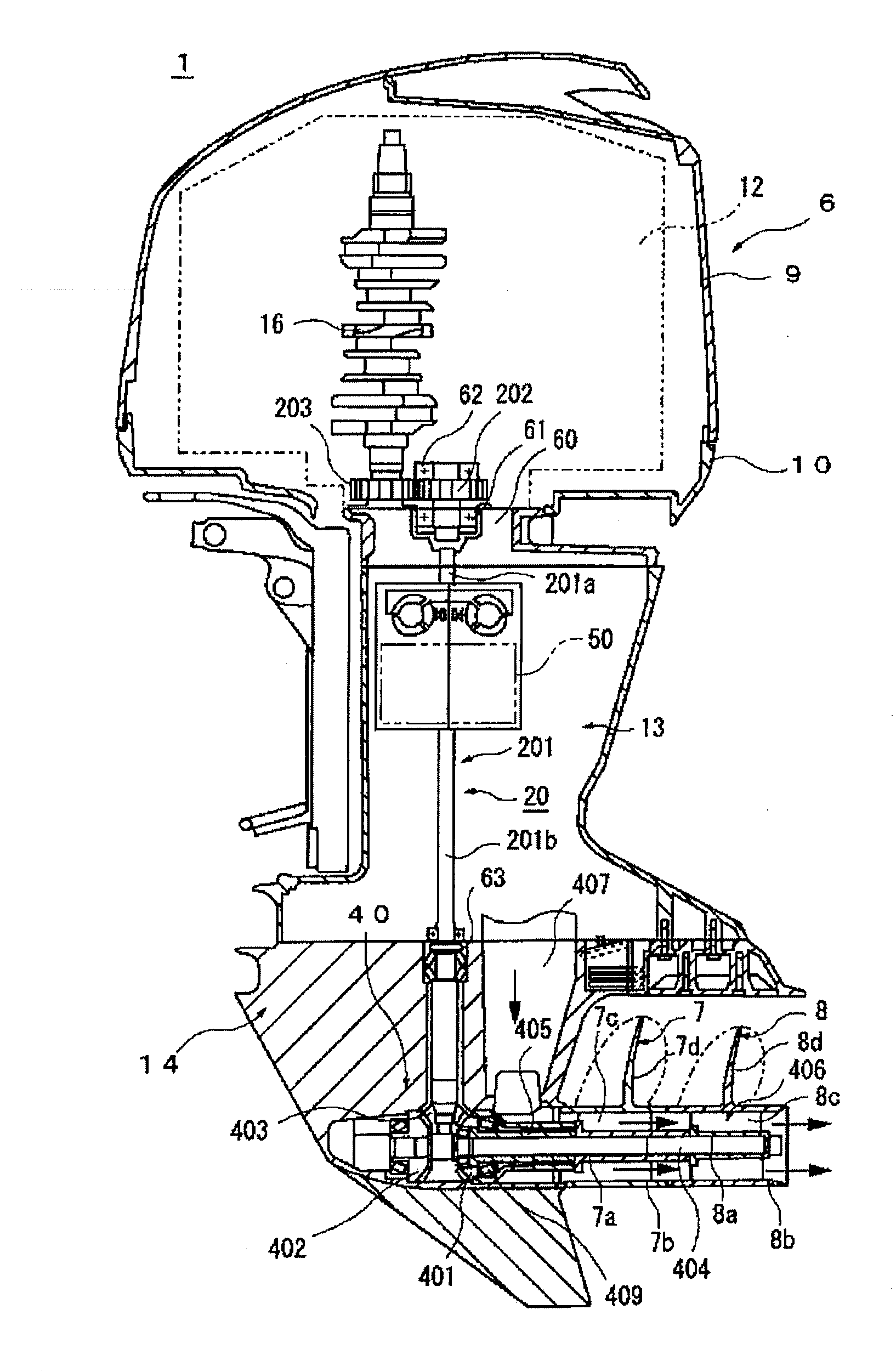
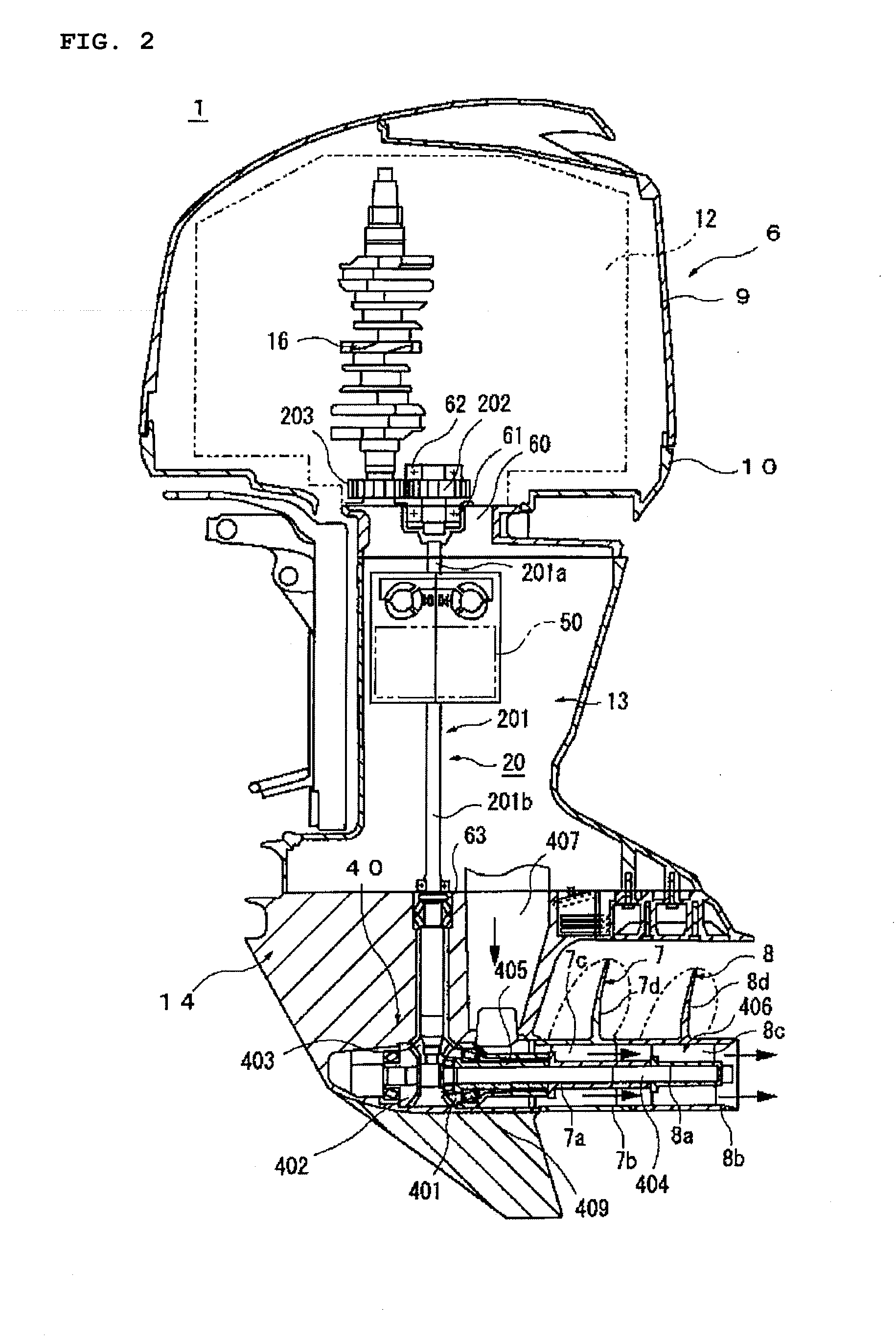
[0048]In the drawings, FIG. 1 is a side view of an outboard motor equipped on a boat, FIG. 2 is a cross-sectional view illustrating a power transmission mechanism and a contra-rotating propeller mechanism of the outboard motor, FIG. 3 is an enlarged view illustrating the contra-rotating propeller mechanism, and FIG. 4 is an enlarged view illustrating the power transmission mechanism.

[0049]As shown in FIG. 1, a boat 1 has a hull 2 with a stern board 2a to which a clamp bracket 4 is secured, and a swivel bracket 5 is attached to the clamp bracket 4 for vertical rotational movement. An outboard motor 6 is attached to the swivel bracket 5 for lateral rotational movement. The outboard motor 6 has a first propeller 7 a...


PUM


Abstract

An outboard motor includes a drive shaft including a pinion gear arranged at one end of the drive shaft, a first driven gear engaged with the pinion gear, a second driven gear engaged with the pinion gear, a first propeller shaft connected to a second propeller, a second propeller shaft connected to a first propeller, and a shift change mechanism arranged to selectively engage the first driven gear with the second propeller shaft, and to selectively engage the second driven gear with the first propeller shaft and with the second propeller shaft.

Description

BACKGROUND OF THE INVENTION[0001]1. Field of the Invention[0002]The present invention relates to an outboard motor, and more particularly to an outboard motor having a transmission ratio changing unit for changing the output from an engine that is transmitted to a propeller.[0003]2. Description of the Related Art[0004]One example of a conventional outboard motor of this type is described in Japanese Patent No. 2686517, which discloses an outboard motor having a first drive shaft connected to the output shaft of the engine, a second drive shaft disposed coaxially with the first drive shaft via a transmission ratio changing unit, and a speed reducing and reversing mechanism for transmitting torque transmitted to the second drive shaft to a propeller shaft.[0005]The transmission ratio changing unit includes first and second planetary gear trains each including a sun gear, a plurality of planetary gears, and an internal gear with which the planetary gears are in meshing engagement.[0006...

Claims


Application Information

Patent Timeline
Patent Type & Authority Applications(United States)
IPC IPC(8): B63H21/21
CPCB63H5/10B63H20/14B63H20/20B63H23/30F16H3/64B63H2023/0258B63H2023/0283B63H2023/305B63H2020/006
Inventor NAKAMURA, DAISUKEOKABE, YOSHIHIKO
Owner YAMAHA MOTOR CO LTD
Why Eureka
Try Eureka