Dynamic spinal stabilization system and method of using the same

a spinal stabilization and dynamic technology, applied in the field of spinal support devices, can solve the problems of limiting the range of motion of the spine, affecting the function of the spinal cord, so as to achieve the effect of increasing the length of the spin

Inactive Publication Date: 2008-09-25
ZIMMER SPINE INC
View PDF19 Cites 141 Cited by
  • Summary
  • Abstract
  • Description
  • Claims
  • Application Information

AI Technical Summary

Benefits of technology

[0011]The stabilization system may include a biasing member for opposing movement of the spring arms away from and / or toward each other. In one embodiment, the biasing member may be configured as a resilient spring ring used when the joint is configured as a hinge. As the spring arms are moved toward or away from each other the spring ring gets compressed to generate a biasing force that opposes the motion. In another embodiment, the biasing member may be configured as a resilient cushion disposed between the spring arms. In this embodiment, the cushion is configured to prevent or reduce compressive overloading of the stabilization system. As such, the cushion imposes a biasing force on the spring arms as they are moved toward each other. In still another embodiment, however, the cushion may include a bridge member that imposes a biasing force as the spring arms are moved away from each other.
[0014]In further embodiments in accordance with the invention, the stabilization system may be incorporated within a larger spinal construct for treatment along an increased length of the spine. The spinal construct may, for example, include both dynamic stabilization portions and rigid stabilization portions, wherein the dynamic stabilization portions may be provided by embodiments of the stabilization systems described herein. To this end, the head portions of the anchors may include a connector that not only couples to the first ends of the flexible construct, but also include a channel or slot for receiving a rigid stabilization rod. This allows the relatively larger spinal construct with modularity with rigid stabilization portions capable of being positioned adjacent the dynamic portions provided by embodiments of the invention.

Problems solved by technology

Patients that suffer from such conditions usually experience extreme and debilitating pain, as well as diminished nerve function.
These spinal disorders, pathologies, and injuries limit the spine's range of motion, or threaten the critical elements of the nervous system housed within the spinal column.
For example, it has been shown that spine fusion decreases function by limiting the range of motion for patients in flexion, extension, rotation and lateral bending.
Furthermore, it has been shown that spine fusion creates increased stresses and therefore, accelerated degeneration of adjacent non-fused segments.
Another disadvantage of fusion is that it is an irreversible procedure.

Method used


Image

  • Dynamic spinal stabilization system and method of using the same
  • Dynamic spinal stabilization system and method of using the same
  • Dynamic spinal stabilization system and method of using the same

Examples


Embodiment Construction

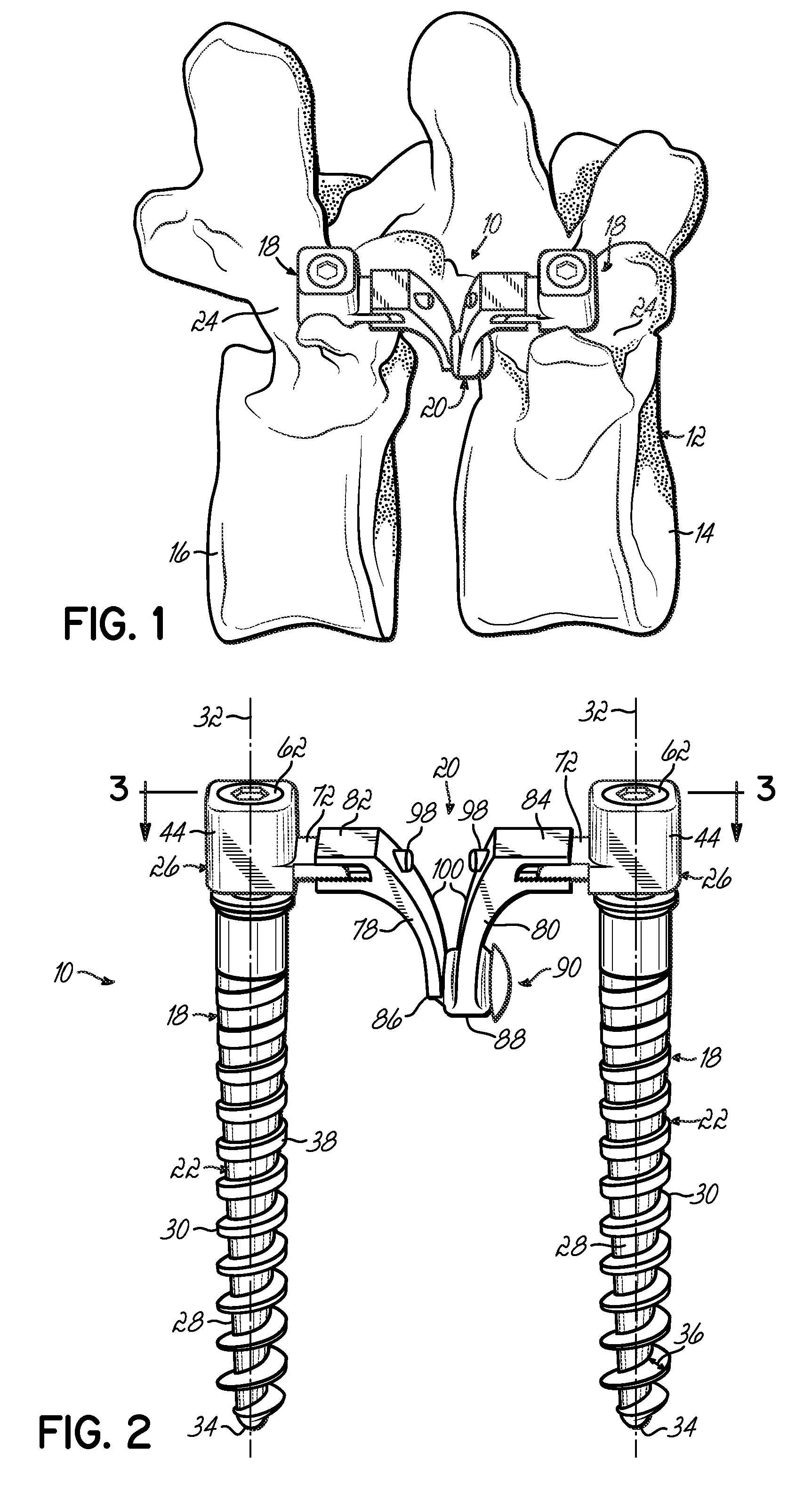
[0030]Referring now to the figures, and to FIG. 1 in particular, a spinal stabilization system 10 is shown implanted into a segment of the spine 12 defined by serially positioned spinal elements in the form of adjacent vertebrae 14, 16 separated by a disc (not shown). The stabilization system 10 includes a pair of anchors 18 installed in vertebrae 14,16 and a flexible construct 20 coupled to and extending between the two anchors 18 to control abnormal motion of the spine 12, while otherwise leaving the spinal segment mobile. In the exemplary embodiment, as well as the other spinal stabilization system embodiments, the flexible construct 20 is configured to more closely align with the natural center of rotation of the spine 12 and can be positioned more anterior relative to the pedicles 24 of the vertebrae 14, 16 to which the anchors 18 are secured.

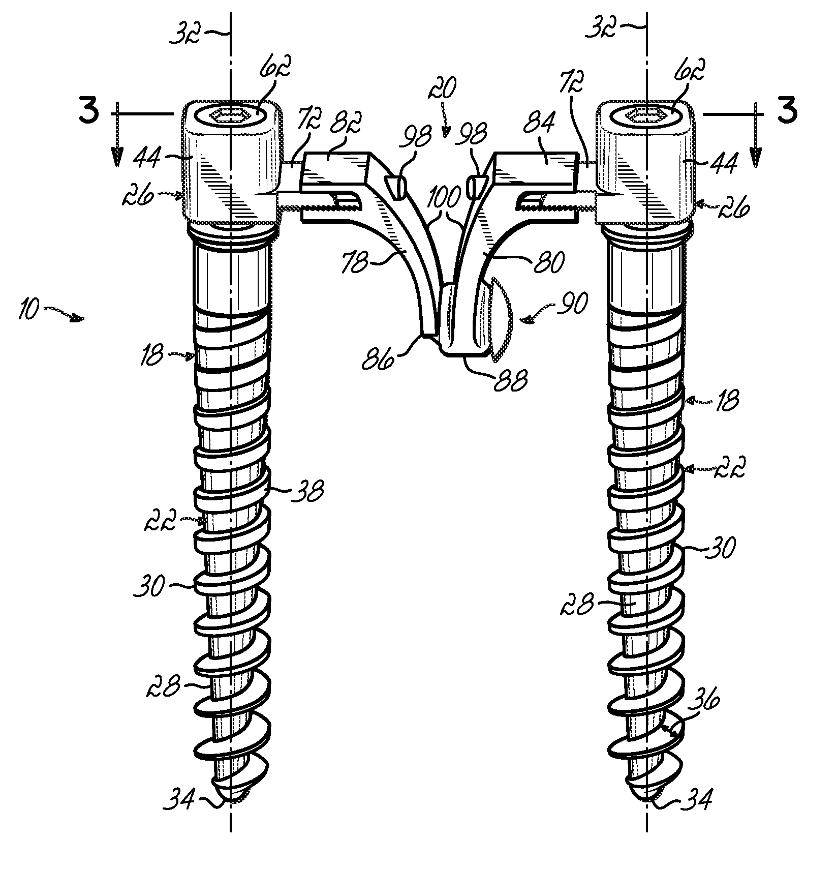
[0031]FIG. 2 illustrates an exemplary embodiment of the spinal stabilization system 10 in more detail. As shown in this figure, each anch...


PUM

PropertyMeasurementUnit
flexibleaaaaaaaaaa
movementaaaaaaaaaa
biasing forceaaaaaaaaaa

Abstract

A spinal stabilization system includes a pair of vertebral anchors and a flexible construct extending between the anchors to provide dynamic stabilization of the spine. The flexible construct includes first and second spring arms coupled to the anchors at first ends thereof and second ends coupled at a joint. The spring arms are capable of flexing toward and away from each other during movement of the spine. The system may include a biasing member for biasing movement of the spring arms toward and / or away from each other. The system may further include an adjustment feature that allows the distraction to be adjusted in situ. The stiffness characteristic of each of the spring arms may be selectively adjusted to meet the specific application. A method of stabilizing a spine includes securing anchors to selected vertebrae and coupling the flexible construct to the anchors through a top loading procedure. The flexible construct may be coupled so that a rotational axis of the flexible construct is anterior of a head portion of the anchors.

Description

FIELD OF THE INVENTION[0001]The present invention generally relates to spinal support devices, and more particularly to an apparatus and method for dynamically stabilizing the spine.BACKGROUND OF THE INVENTION[0002]The spinal column is a highly complex system of bones and connective tissues that provides support for the body and protects the delicate spinal cord and nerves. The spinal column includes a series of vertebrae stacked one on top of the other, each vertebral body including an anterior portion of relatively weak cancellous bone and a posterior portion of relatively strong cortical bone. Situated between each vertebral body is an intervertebral disc that cushions and dampens compressive forces experienced by the spinal column. A vertebral canal containing the spinal cord and nerves is located behind the vertebral bodies. In spite of the complexities, the spine is a highly flexible structure, capable of a high degree of curvature and twist in nearly every direction. For exam...

Claims


Application Information

Patent Timeline
Patent Type & Authority Applications(United States)
IPC IPC(8): A61B17/70A61B17/58A61B17/04
CPCA61B17/7007A61F2310/00796A61B17/7026A61B17/7035A61B17/863A61F2/4405A61F2002/30176A61F2002/30331A61F2002/30448A61F2002/30457A61F2002/30471A61F2002/30492A61F2002/305A61F2002/30507A61F2002/30517A61F2002/30522A61F2002/30546A61F2002/3055A61F2002/30556A61F2002/30563A61F2002/30571A61F2002/30578A61F2002/30649A61F2002/448A61F2002/449A61F2220/0025A61F2220/0033A61F2220/005A61F2220/0058A61F2220/0091A61F2230/0054A61F2250/0009A61F2250/0012A61B17/7023A61F2002/30451
Inventor HUDGINS, R. GARRYLVIKER, THOMAS O.CASUTT, GUIDO
Owner ZIMMER SPINE INC
Why Eureka
Try Eureka