
Laboratory instrumentation information management and control network

a laboratory instrument and information management technology, applied in the field of data management, can solve the problems of increasing the amount of time it takes to process samples, wasting significant time and energy, and unable to manage workflows of certain laboratory instruments

Inactive Publication Date: 2008-09-25
VENTANA MEDICAL SYST INC
View PDF121 Cites 133 Cited by
  • Summary
  • Abstract
  • Description
  • Claims
  • Application Information

AI Technical Summary

Benefits of technology

The invention provides a method for identifying and tracking biological samples in a laboratory using harmonized identifiers. These identifiers are unique to each sample and are associated with information about the patient and the processing of the sample. The method includes recording data on a server about each sample, including a case identifier, a specimen identifier, and a block identifier. The server also records data about the cassette or slide used to process the sample. The harmonized identifiers can be used to differentiate between different samples in a laboratory and to track the processing of each sample. The method helps to improve the efficiency and accuracy of processing samples in a laboratory.

Problems solved by technology

Unfortunately, however, current Laboratory Information Systems tend to lack the ability to manage workflow with certain laboratory instrumentation, such as, for example, an advanced staining instrument.
As such, there exist several deficiencies in how these instruments are utilized in the laboratory.
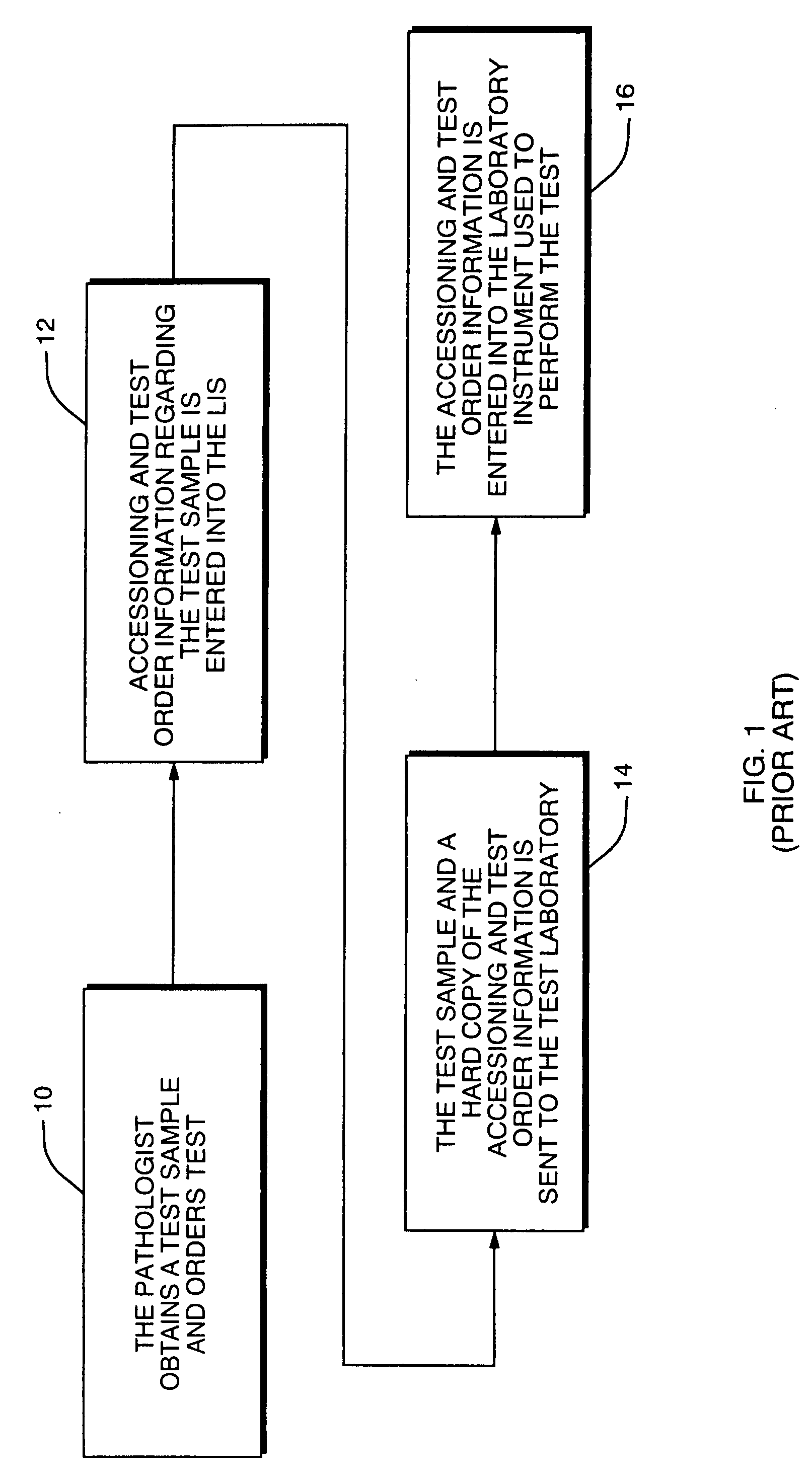
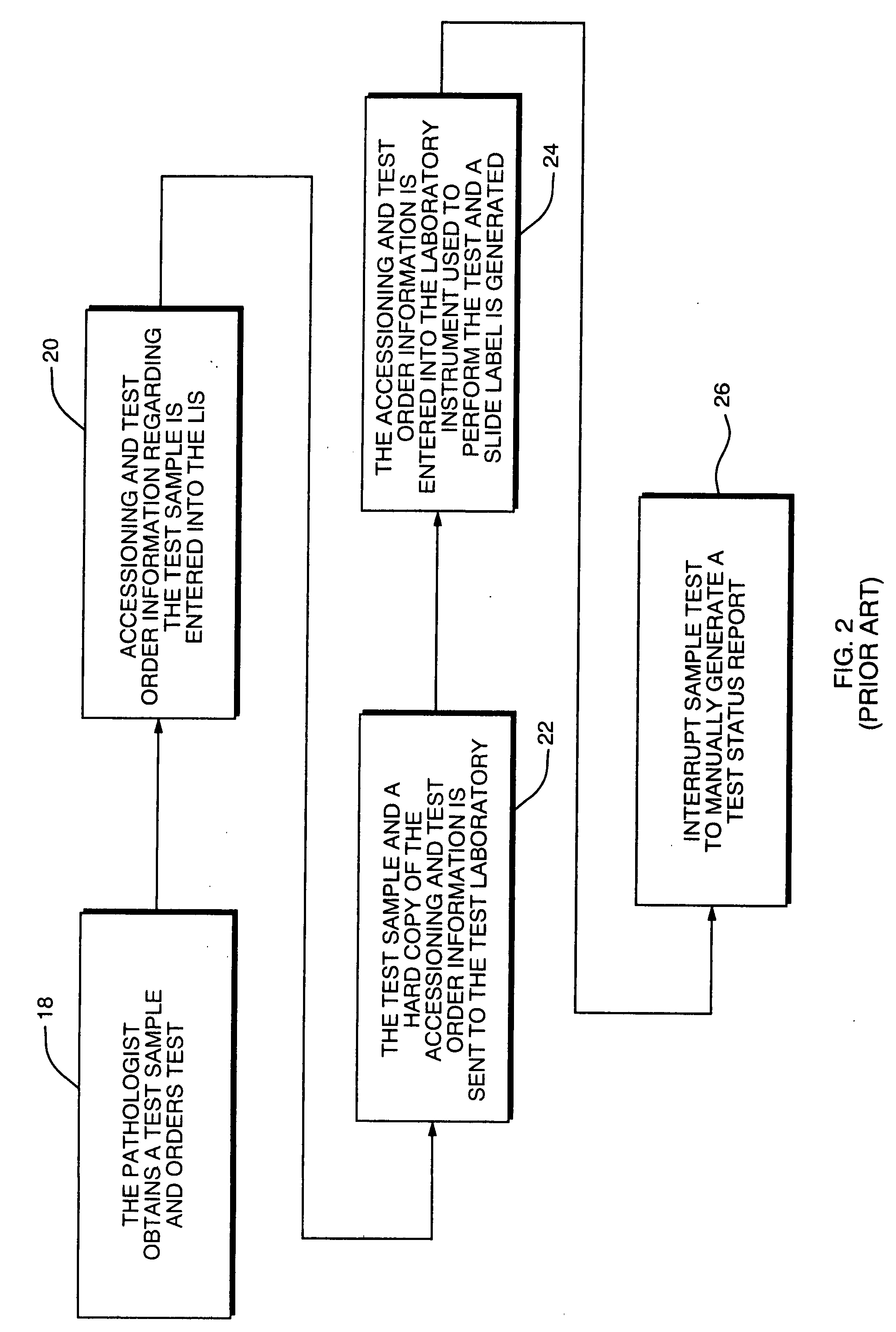
A significant amount of time and energy is expended replicating tedious functions, such as data entry, labeling and manual entry for report generation.
This replication increases the amount of time it takes to process samples by creating a significant bottleneck in laboratory work flow.
The tedious nature of these tasks can substantially increase errors and can affect the accuracy of the diagnostic process.
The resulting increase in test completion time may allow a localized disease to progress into systemic proportions, such as a localized tumor metastasizing, having a devastating effect on patient prognosis and / or treatment options and results.
This could take a significant amount of time depending on the number of samples and the extent of testing being performed on the samples.
Additionally, each time this data entry function is replicated, the possibility of error in the information transfer increases, reducing the accuracy and reliability of the testing procedure.
Unfortunately however, the lack of data communications between the LIS and the laboratory instruments prevents test status monitoring by precluding the automatic generation of a test status report.
In addition to this lack of connectivity creating a bottleneck in laboratory work flow, the diagnostic capability of the laboratory is also adversely affected due to the reality that current laboratory set-ups do not have the ability to perform many new and advanced features which may substantially increase the timeliness, reliability and accuracy of new and existing tests.
Unfortunately however, a suitable system management structure does not exist that would allow for effective control between the LIS and automated laboratory instrumentation, such as staining instrumentation, such that the timeliness of the test performance, data analysis, disease diagnosis and information dissemination process is substantially optimized.
Additionally, known systems for interconnecting laboratory instrumentation and information systems do not effectively and automatically identify, prioritize and stage specimens to optimize the throughput and utilization of the automatic staining systems.
Nor do known systems have the capability to automate the identification, labeling and tracking of specimens and results through the clinical pathology process.
Furthermore, known systems are not specifically capable of optimizing the storage, use, and management of the reagents between staining systems necessary for performing the multitude of staining procedures for disease diagnosis.

Method used


Image

  • Laboratory instrumentation information management and control network
  • Laboratory instrumentation information management and control network
  • Laboratory instrumentation information management and control network

Examples


embodiment 1000

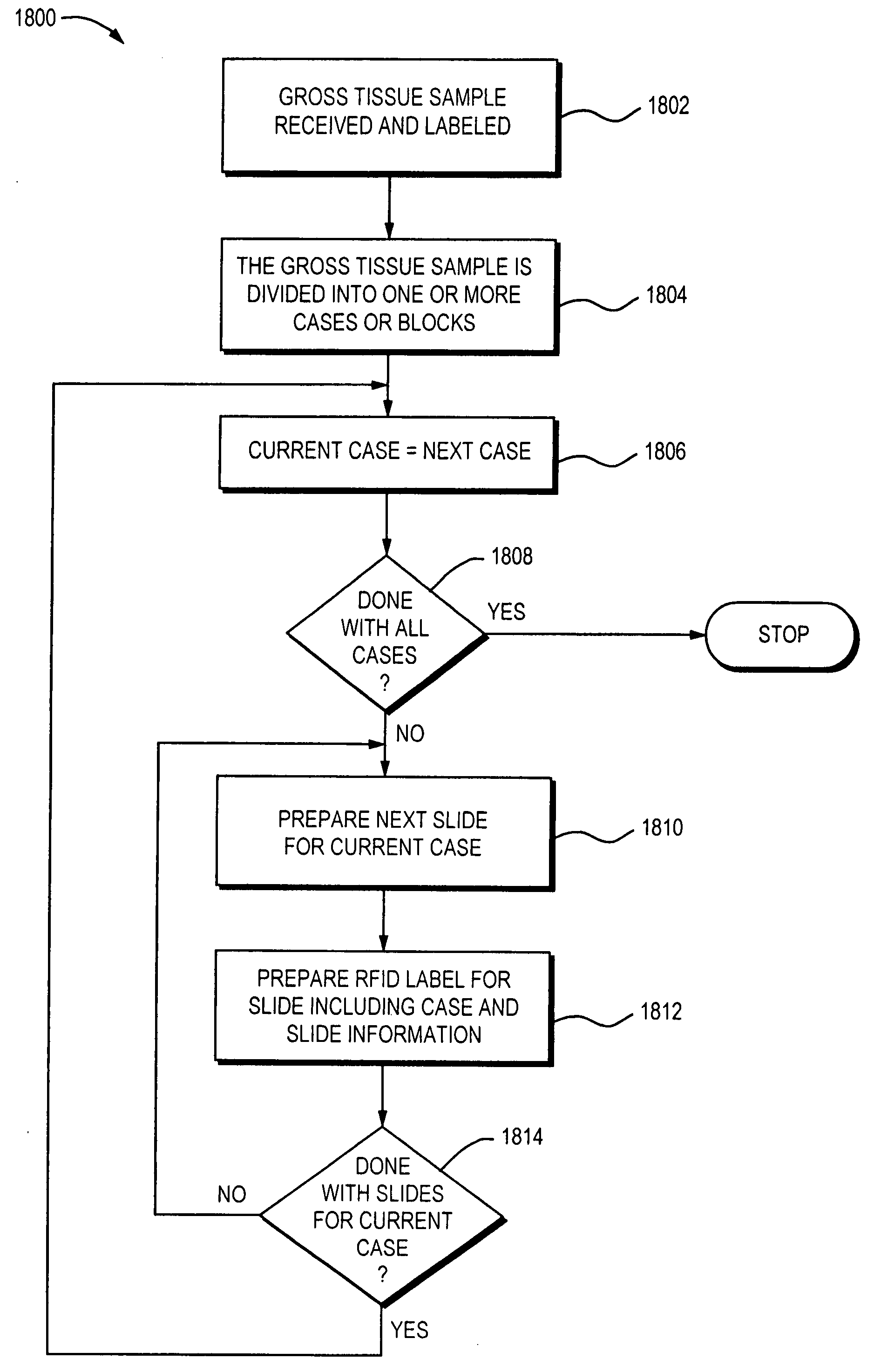
[0207]Referring now to FIG. 9, shown is an example of an embodiment 1000 of a slide arrangement. The slide 1004 includes an RFID label 1002. In the arrangement 1000, the RFID label 1002 is affixed to an upper face 1006 of the slide 1004. The slide in this arrangement and others described herein may be, for example, a glass slide. The RFID label 1002 may include information electronically encoded therein as described elsewhere herein. Additionally, a surface of the RFID label 1002 may include printed information such as, for example, human readable text, bar code identifiers, and the like. It should also be noted that an embodiment of an RFID label 1002 may omit the inclusion of text or other type of information on the surface thereof.

[0208]Referring now to FIG. 10, shown is a second arrangement 1020 of a slide and an RFID label. In the example 1020, the slide 1024 includes an RFID label 1022 affixed to a lower surface 1026 of the slide 1024. In this example arrangement 1020, the sli...

first embodiment

[0268]In one embodiment, a host may elect to share data on a data element-by-data element basis. This allows the host to control its own use of each data element. Each host controls whether a particular data element is used at all by that host. If a data element is used, the host controls whether this data element is locally (e.g., on only this host) or globally defined (e.g., available to other hosts). The particular data elements shared among one or more hosts may reflect the functionality of the hosts and / or its associated instruments. An embodiment may have the same or different functionality associated with each of the hosts. For example, in a first embodiment, the functionality may be the same on each host. A first host and a second host may elect to share the same data elements when the first and second hosts support the same set of instruments and operations. In another embodiment, the functionality of each host may vary, for example, if the first and second hosts support di...


PUM


Abstract

Described are techniques for identifying samples processed in a laboratory using harmonized identifier. A case identifier identifying a patient from whom a specimen is collected is determined. A specimen identifier associated with the specimen is determined. An entry for the specimen is recorded in a data store where the entry being associated with the case identifier and the specimen identifier. A harmonized specimen identifier including the case identifier and the specimen identifier is formed. The specimen is labeled with the harmonized specimen identifier.

Description

CROSS REFERENCE TO RELATED APPLICATIONS[0001]This application is a continuation-in-part of U.S. patent application Ser. No. 11 / 032,324, filed, Jan. 10, 2005, Attorney Docket No. VMS-002US, which is a continuation-in-part of U.S. patent application Ser. No. 10 / 893725, filed Jul. 16, 2004, Attorney Docket No. VMS-00101, which claims the benefit of U.S. Provisional Application No. 60 / 487,998, filed Jul. 17, 2003, Attorney Docket No. VMS-00160, and is a continuation-in-part of U.S. patent application Ser. No. 11 / 639,586, AUTOMATED LEAN METHODS IN ANATOMICAL PATHOLOGY, filed Dec. 15, 2006, Attorney Docket No. VMS-003US, which claims the benefit of U.S. Provisional Patent Application No. 60 / 751,807, filed on Dec. 19, 2005, entitled AUTOMATED LEAN METHODS IN ANATOMICAL PATHOLOGY, Attorney Docket No. 310 / 003 / PPA, all of which are incorporated by reference herein.BACKGROUND OF THE INVENTION[0002]1. Technical Field[0003]This invention relates generally to data management and more particularly...

Claims


Application Information

Patent Timeline
Patent Type & Authority Applications(United States)
IPC IPC(8): G06Q50/00G06F17/30G06F17/40
CPCG01N35/00732G06Q10/10G06F19/366G06Q50/24G06Q50/22G16H10/40
Inventor MATTINGLY, SCOTTLARSON, ALAINMESSICK, BRIANPHILLIPS, JACKSTEPHENS, RANDYCRAWFORD, WILLIAM C.EWONIUK, AARON
Owner VENTANA MEDICAL SYST INC
Learn More