
Peripheral Interface, Receiving Apparatus and Data Communication Method Using the Same

a technology of receiving apparatus and data communication method, applied in the field of data transmission, can solve the problems of increased chip size and pin number, poor continuity of data transmission, and unnecessary cost, and achieve the lowest efficiency of mmis interface, reduce chip size and pins, and avoid unnecessary cost

Inactive Publication Date: 2008-09-25
INNOFIDEI TECHNOLOGIES INC
View PDF4 Cites 16 Cited by
  • Summary
  • Abstract
  • Description
  • Claims
  • Application Information

AI Technical Summary

Benefits of technology

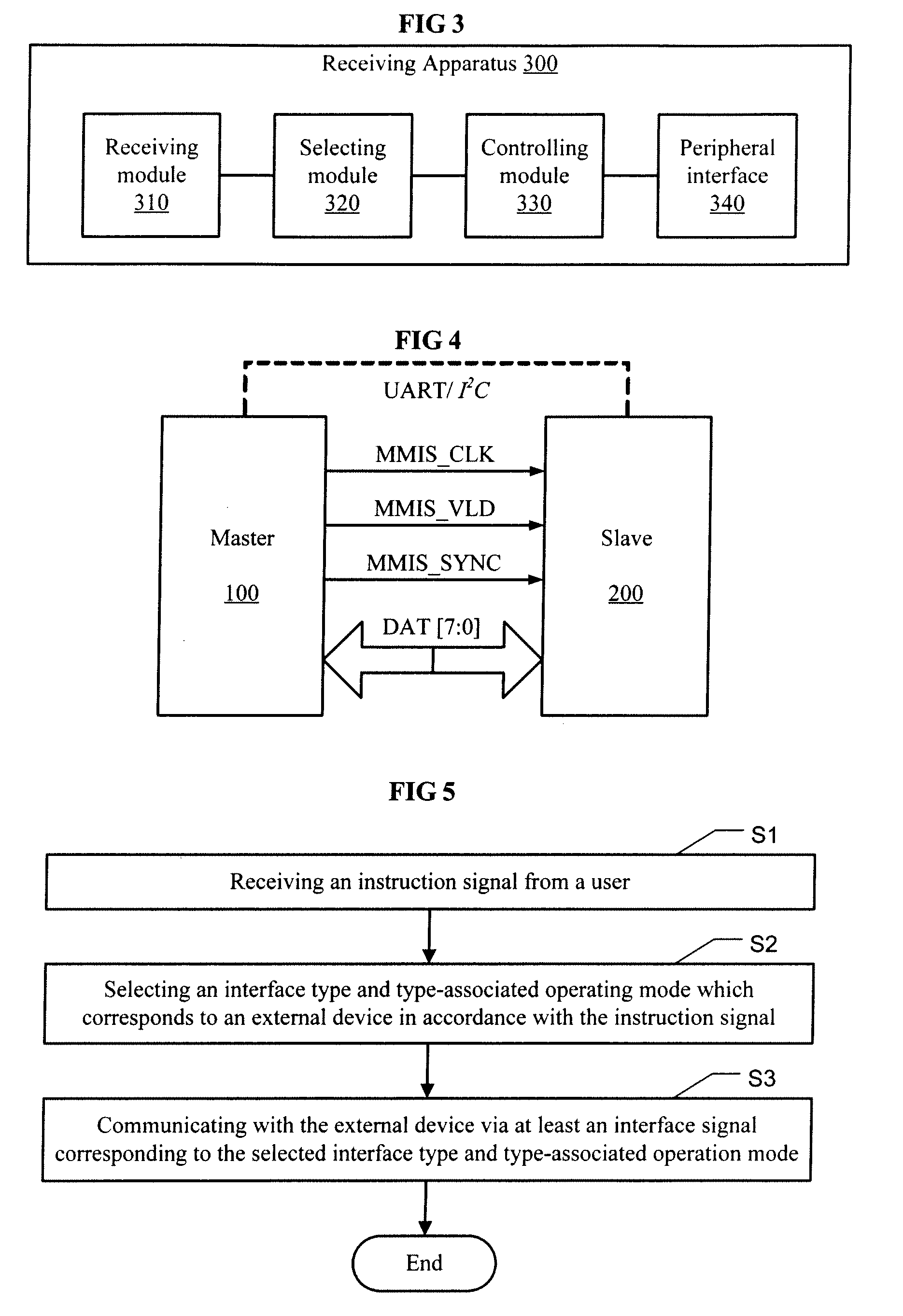
[0014]For the case that various types of interfaces may be supported, the present invention proposes a peripheral interface that can multiplex a plurality of interfaces. According to an instruction signal from a user, the receiving apparatus of the present invention selects an interface type and type-associated operating mode which are in accordance with an external device to be connected, and controls the peripheral interface of the present invention to communicate with the external device via at least one interface signal corresponding to the selected interface type and type-associated operating mode. In this way, it achieves the multiplexing of interfaces of various types, and thereby the size and pins of the chip can be reduced. At the same time, unnecessary cost can be avoided.
[0015]With an example that the peripheral interface of the present invention is a Mobile Multimedia Interface System (MMIS) interface that multiplexes SPI, SDIO interface, and Digital Video Broadcasting Transmission Socket (DVB-TS), Table 1 shows the performance of the MMIS interface. As shown in the Table 1, the SPI, SDIO interface, and DVB-TS are multiplexed together effectively. As the Table 1 shows the likely lowest efficiency of the MMIS interface in each one of the operating modes which supports 16-bit and 32-bit transmission mode, and the data transmission efficiency for these operating modes is relatively high.TABLE 1MMISConnect withOperating modeSPI / SDIO interface devicePerformanceEfficiencyOperating1-1Compatible with single-channelMaximum50% for unidirectionmode 1SPI interface device13.5 Mbit / s1-2Compatible with single-channelMaximum50% for unidirectionSDIO interface device (normal13.5 Mbit / sdevice e.g., memory card)Operating mode 2Compatible with double-channelMaximum50% for bi-directionSPI interface device (e.g., AP,13.5 Mbit / sEEPRO and so on)Operating3-1Compatible with four-channelMaximum50% for unidirectionmode 3SPI interface device54 Mbit / s3-2Compatible with four-channelMaximum50% for unidirectionSDIO interface device54 Mbit / sOperating mode 4Compatible with DVB-TSMaximum100%interface device108 Mbit / s
[0016]At the same time, another object of the present invention is to raise the data throughput of peripheral interface, such that the requirement for transmitting data with great flow may be satisfied.
[0017]In order to attain the above object, another embodiment of the present invention discloses a preferable peripheral interface of the above, wherein the types of the interfaces multiplexed by the pins of the peripheral interface include at least two selected from a group including SPI, SDIO interface, and DVB-TS; the type-associated operating modes of the SPI include single-channel, double-channel, and four-channel SPI; the type-associated operating modes of the SDIO interface include single-channel and four-channel SDIO interface; the type-associated operating modes of the DVB-TS include DVB-TS; and among the interfaces multiplexed by the peripheral interface (e.g., a MMIS interface), respective type-associated operating modes of the SPI, the SDIO interface and the DVB-TS are multiplexed.
[0018]By providing the operating modes of four-channel SPI and four-channel SDIO interface, the present invention can raise the data throughput of the peripheral interface effectively. For example, as shown in the Table 1, while the peripheral interface is operating in the operating mode of four-channel SPI, the data rate thereof rises to 54 Mb / s, and it is three times higher than that of the operating mode of double-channel SPI.
[0019]It is appreciated for a skilled in the art that the feature of the operating mode of four-channel SPI and four-channel SDIO interface can be supplemented into the receiving apparatus and the data communication method of the present invention too, and the same advantageous effect can be obtained. No more explanation of the supplementation is repeated hereafter.

Problems solved by technology

However, in a case that interfaces of different specifications contained on a chip are completely independent of each other, the size of the chip and the number of pins will be increased significantly, resulting in unnecessary cost.
Therefore, the continuity of data transmission is poor.
Although an identical pin may be configured on a command layer to transmit signals with different purposes, the configuration of an identical pin transmitting signals with different purposes on the command layer has complexity in some extent.
Meanwhile, as the identical pin is configured on the command layer to transmit signals with different purposes, transmission errors are usually inevitable which causes the slave equipment hardly to be enabled.
Furthermore, the data throughput in the existing operating modes of single-channel SPI and double-channel SPI is relatively small, such that the requirement for transmitting data with large traffic is difficult to be satisfied.

Method used


Image

  • Peripheral Interface, Receiving Apparatus and Data Communication Method Using the Same
  • Peripheral Interface, Receiving Apparatus and Data Communication Method Using the Same
  • Peripheral Interface, Receiving Apparatus and Data Communication Method Using the Same

Examples


first embodiment

THE FIRST EMBODIMENT

[0056]In a case that the MMIS interface is operating in an operating mode of single-channel SPI or single-channel SDIO interface, FIG. 6 shows the connection relation between the master equipment 100 and the slave equipment 200. As shown in FIG. 6, pins connected between these two comprise: MMIS_CLK pin of the MMIS interface, MMIS_D3 (MMIS_CS) pin of the MMIS interface, MMIS_VLD (MMIS_CMD / MMIS_RXD) pin of the MMIS interface, MMIS_D1 (MMIS_IRQ) pin of the MMIS interface, and MMIS_D0 (MMIS_TRXD) pin of the MMIS interface.

[0057]In detail, when the MMIS interface is operating in the operating mode of single-channel SPI, as shown in Table 2, the corresponding interface signals transmitted by the pins of the MMIS interface are defined in a manner as follows:

[0058]a clock signal is transmitted by the MMIS_CLK pin of the MMIS interface;

[0059]an indication signal of multiplexed frame header is transmitted by the MMIS_SYNC pin of the MMIS interface;

[0060]data is transmitte...

second embodiment

THE SECOND EMBODIMENT

[0078]In a case that the MMIS interface is operating in an operating mode of double-channel SPI, FIG. 7 shows the connection relation between the master equipment 100 and the slave equipment 200. As shown in FIG. 7, pins connected between these two comprise: MMIS_CLK pin of the MMIS interface, MMIS_D3 (MMIS_CS) pin of the MMIS interface, MMIS_VLD (MMIS_CMD / MMIC_RXD) pin of the MMIS interface, MMIS_SYNC pin of the MMIS interface, MMIS_D0 (MMIS_TRXD / MMIS_TXD) pin of the MMIS interface, and MMIS_D1 (MMIS_IRQ) pin of the MMIS interface.

[0079]In detail, when the MMIS interface is operating in the operating mode of double-channel SPI, as shown in Table 3, the corresponding interface signals transmitted by the pins of the MMIS interface are defined as follows:

[0080]a clock signal is transmitted by the MMIS_CLK pin of the MMIS interface;

[0081]data is inputted by the MMIS_VLD (MMIS_CMD / MMIC_RXD) pin of the MMIS interface;

[0082]an instruction signal of multiplexed frame h...

third embodiment

THE THIRD EMBODIMENT

[0093]Due to the relatively small data throughput of the operating modes of single-channel and double-channel SPI, the present invention proposes an operating mode of four-channel which comprises four pins for receiving / transmitting data.

[0094]In a case that the MMIS interface is operating in the operating mode of four-channel SPI or four-channel SDIO interface, the connection relation between the master equipment 100 and the slave equipment 200 is shown in FIG. 8. As shown in FIG. 8, pins connected between these two comprise: MMIS_CLK pin of the MMIS interface, MMIS_VLD (MMIS_CMD / MMIC_RXD) pin of the MMIS interface, MMIS_SYNC pin of the MMIS interface, MMIS_D1 (MMIS_IRQ) pin of the MMIS interface, MMIS_D0 (MMIS_TRXD / MMIS_TXD) pin of the MMIS interface, MMIS_D2 (MMIS_RW) pin of the MMIS interface, MMIS_D3 (MMIS_CS) pin of the MMIS interface, and MMIS_D4 (MMIS_IRQ) pin of the MMIS interface.

[0095]In detail, when the MMIS interface is operating in the operating mod...


PUM


Abstract

Peripheral interface(s), a receiving apparatus and a data communication method using the same are disclosed. According to an embodiment of the present invention, a peripheral interface comprises one or more pins for multiplexing at least two types of interfaces, wherein the pins transmit interface signals corresponding to an interface type and type-associated operating mode which are selected from those multiplexed by the pins. According to another embodiment, a receiving apparatus comprises: a peripheral interface for multiplexing at least two types of interfaces; a receiving module for receiving an instruction signal; a selecting module for selecting an interface type and type-associated operating mode which corresponds to an external device to be connected, based on the instruction signal; a controlling module for controlling the peripheral interface to communicate with the external device via at least one interface signal corresponding to the selected interface type and type-associated operating mode.

Description

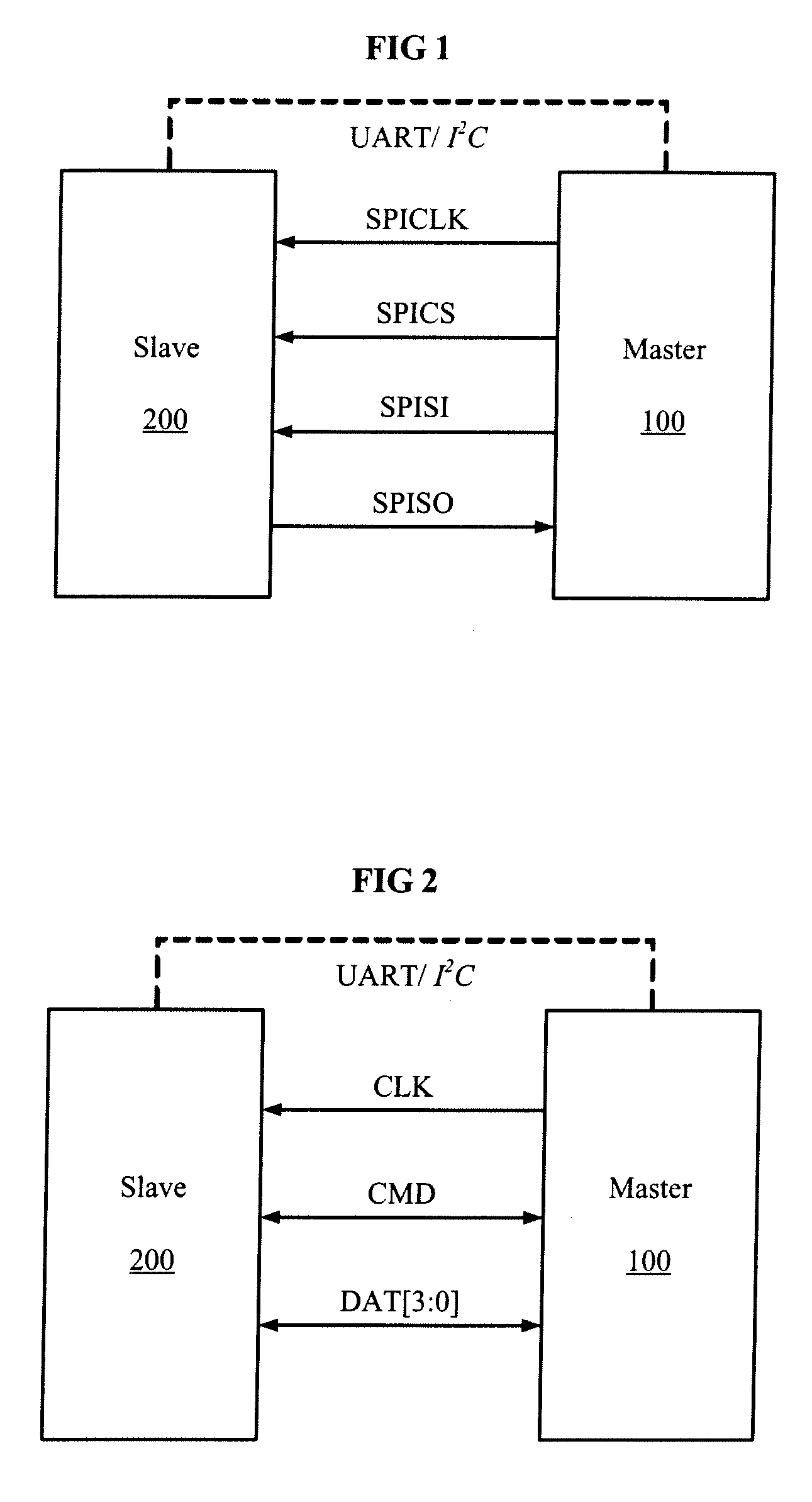
FIELD OF THE INVENTION[0001]The present invention relates to data transmission field, and in particular, relates to peripheral interface(s), a receiving apparatus and a data communication method using the same.BACKGROUND OF THE INVENTION[0002]A Serial Peripheral Interface (SPI) bus system is a synchronous serial peripheral interface allowing a master equipment to communicate and exchange data with multiple types of slave equipments in serial manner. The SPI system has two different operating modes of single-channel and double-channel SPI, wherein the operating mode of double-channel is used mostly. The SPI system is applicable to configure ports with Inter-Integrate Circuit (I2C) bus or Universal Asynchronous Receiver Transmitter (UART) bus. As shown in FIG. 1, based on the operating mode of double-channel SPI, there are 4 lines mainly applied between the master equipment 100 (i.e., SPI apparatus) and the slave equipment (SALVE) 200 (e.g., PDA) and including: Serial Peripheral Inter...

Claims


Application Information

Patent Timeline
Patent Type & Authority Applications(United States)
IPC IPC(8): G06F13/28
CPCG06F2213/0016G06F13/4291G06F13/14
Inventor ZHANG, HUIDENG, YUNQINGJIANG, KEHU, WEI
Owner INNOFIDEI TECHNOLOGIES INC
Learn More