Wire rope for running wire

Active Publication Date: 2008-10-02
TOKYO ROPE MFG
View PDF5 Cites 16 Cited by
  • Summary
  • Abstract
  • Description
  • Claims
  • Application Information

AI Technical Summary

Benefits of technology

[0010]The invention has been carried out in order to resolve the above-described problem and it is an object thereof to provide a wire rope for a running wire capable of promoting fatigue life by reducing a wire brea

Problems solved by technology

However, according to the structure, metal contact is unavoidable between the strands, between a sheave portion and the rope and disconnection by wear is brought about.
Although a number of prior arts have been proposed as a countermeasure thereagainst, problems are posed by the respective prior arts and the prior arts cannot be regarded as sufficient yet.
According to Japanese Patent No. 2876140 (Prior Art 1), a core rope is thinly coated with a resin, and there poses a problem that although disconnection by wear between the core rope and a side strand can be avoided, disconnection by wear between strands and at a contact face with a sheave cannot be avoided.
However according to the prior art, a base end portion of the spacer is formed by a wedge-like shape, the wedge portion reaches a center of the rope, and therefore, an effective sectional area of the rope is reduced to pose a problem that it is difficult to use the rope for a use requesting a high breaking

Method used


Image

  • Wire rope for running wire
  • Wire rope for running wire
  • Wire rope for running wire

Examples


examples

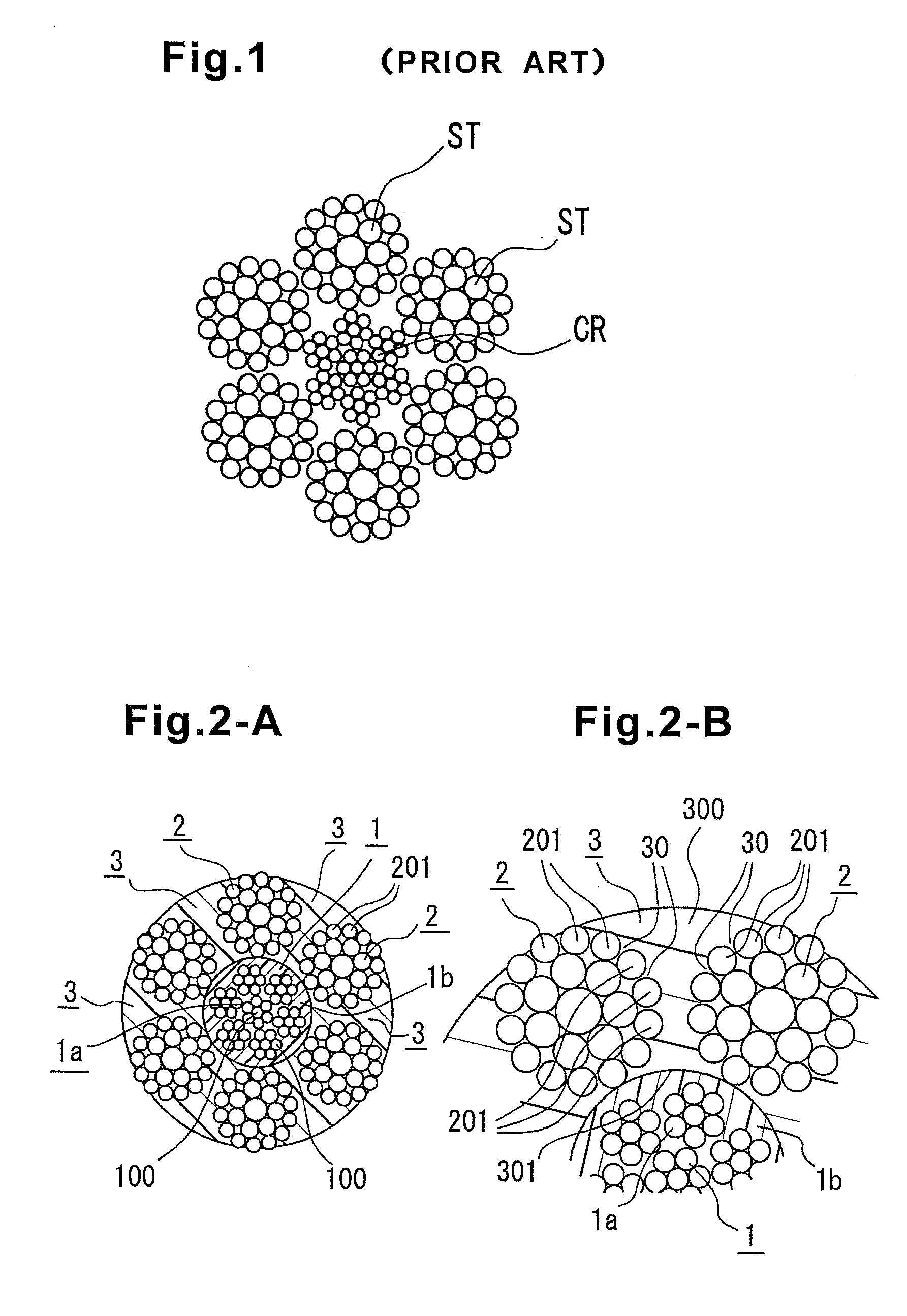
[0057]There is fabricated a rope having a structure of IWRC 6×Fi (29) shown in FIG. 2-A, having 0 / 0, diameter 16 mm, a tensile strength 173kN. There is used a core rope having a diameter 7.5 mm coated with polypropylene resin by an extruding mold machine at an outer periphery of a core rope main body. 6 pieces of side strands having a diameter of 5.01 mm are used.

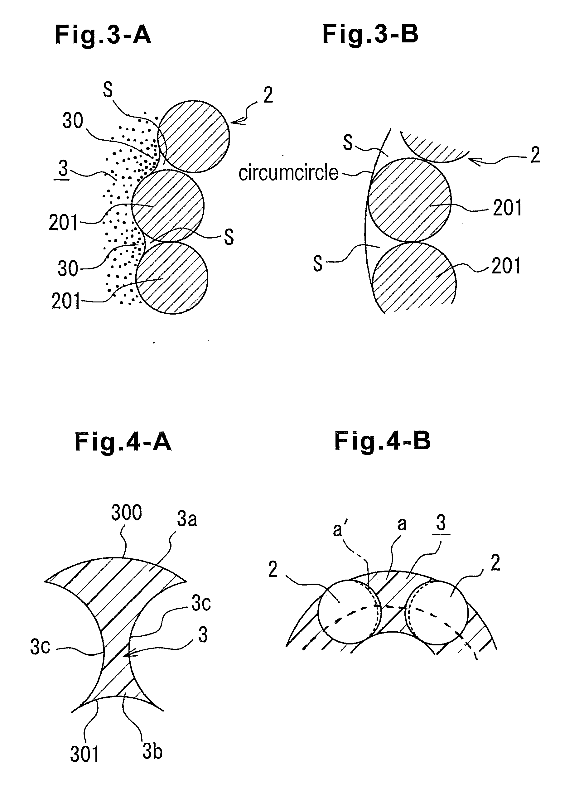
[0058]As a resin spacer, there is used a streak member constituted by subjecting polypropylene resin to extrusion molding. The resin spacer is provided with a sectional shape shown in FIG. 4-A, and when a gap of arranging wire cores of the side strands is constituted by 100, a thickness thereof is constituted by a dimension of 125% thereof. The resin spacer is inserted between the side strands by the method of FIG. 5 and is plastically deformed by exerting a compression force in a radius direction by a vise. In order to investigate a preferable condition, a radius direction compression degree is changed by variously constit...


PUM

PropertyMeasurementUnit
Fractionaaaaaaaaaa
Fractionaaaaaaaaaa
Forceaaaaaaaaaa

Abstract

In a rope of a type of filling a resin constituting other member between strands, there is provided a wire rope for a running wire capable of promoting fatigue life by reducing a wire breakage at a point of being contacted to a core rope by precisely constraining a movement of a wire and reducing an elongation.
A rope having a core rope and a plurality of pieces of side strands arranged at an outer periphery thereof and twisted together, and a resinous spacer interposed between the side strands, in which the core rope includes a rope main body and a resin coating layer outwardly surrounding the core rope main body, the core rope main body and the side strand are separated by the resin coating layer, and the resin spacer is provided with a contour in correspondence with an outer layer wire of the side strand and invades between the wires.

Description

TECHNICAL FIELD[0001]The present invention relates to an improvement in a wire rope for a running wire.BACKGROUND ART[0002]re are very many kinds of wire ropes and it is well known that when a wire rope is used, unless a wire rope adapted to an object thereof and a place of use is selected, an advantage provided to a wire rope cannot sufficiently be utilized.[0003]Particularly, a wire rope for a running wire in a crane or the like is bent by a sheave and is wound to a drum, and therefore, a fatigue resistance characteristic is requested.[0004]In a background art, according to a rope of this kind, as shown by FIG. 1, there is adopted a structure of arranging a plurality of pieces of side strands ST at an outer periphery of a core rope CR to be twisted, and a fiber core or a metal core is used for the core rope. However, according to the structure, metal contact is unavoidable between the strands, between a sheave portion and the rope and disconnection by wear is brought about.[0005]A...

Claims


Application Information

Patent Timeline
IPC IPC(8): D07B1/06D07B1/16D07B7/00D01D5/00
CPCD07B1/0673D07B1/165D07B1/167D07B3/04D07B3/06D07B2201/1032D07B2201/1036D07B2201/104D07B2201/2059D07B2201/2062D07B2201/2065D07B2201/2073D07B2201/2074D07B2201/2075D07B2501/2076D07B2201/2037
Inventor FURUKAWA, IPPEIIDA, SHUJI
Owner TOKYO ROPE MFG
Why Eureka
Try Eureka