Material failure prediction/stress/strain detection method and system using deformation luminescence

a technology of deformation luminescence and material failure, applied in the field of material failure prediction/stress/strain detection method and system using deformation luminescence, can solve the problems of inability of scientists to accurately detect structural stress, systematic fatigue is nearly impossible to detect, and ineffective techniques, in general, to achieve the effect of improving the indication of material fatigue and assessing the overall health of the material

Inactive Publication Date: 2008-10-02
WOO GEOFFREY
View PDF5 Cites 12 Cited by
  • Summary
  • Abstract
  • Description
  • Claims
  • Application Information

AI Technical Summary

Benefits of technology

[0009]In accordance the invention, a method is provided for, inter alia, predicting material failure and for providing an improved indication of material fatigue by correlating photon emissions to stress and strain. Broadly speaking, by analyzing the emissions (preferably, photonic emissions and, more preferably, deformation luminescence) from a material under test, the overall health of the material can be assessed

Problems solved by technology

For years, the fields of aerospace and structural engineering have been hindered by the inability of scientists to accurately detect structural stress, to analyze the degrading effects of long-term fatigue, and, most importantly, to predict when a structure or structural member will break or fail.
Particularly in the cases of advanced composites for military aircraft and aluminum engines for high performance automobiles, systematic fatigue is nearly impossible to detect (see Case, S W., and K L. Reifsnider. Fatigue of Composite Materials.
This technique is, in general, ineffective because all materials have a normal elastic range, and it is difficult to immediately distinguish the change from the elastic region to the plastic region (see Hookes Law—Strength (Mechanics) of Materials.
Further, this method does not determine internal damage nor does it show stress levels within the interior of the material.
As designers and engineers push their creations to their design limits, the increasing stress demands for engines, aircraft, and skyscrapers spawn problems such that a single deformed bolt could lead to failure and disaster.
The inability to detect material stress can effectively mean the difference between life and death.
Substantial resources have been spent on costly reconstructions and improvements.
However, even the most advanced materials weaken and it is inevitable that repairs and replacements are needed.

Method used


Image

  • Material failure prediction/stress/strain detection method and system using deformation luminescence
  • Material failure prediction/stress/strain detection method and system using deformation luminescence
  • Material failure prediction/stress/strain detection method and system using deformation luminescence

Examples


Embodiment Construction

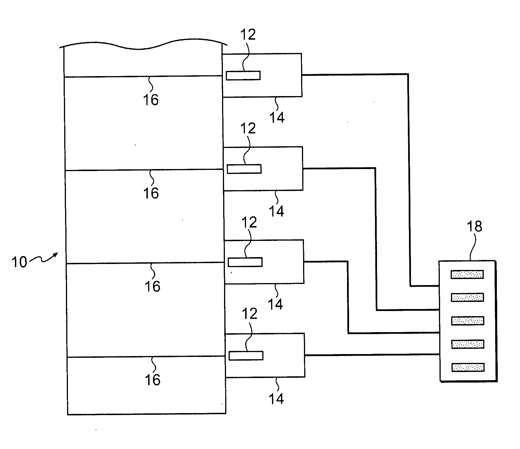
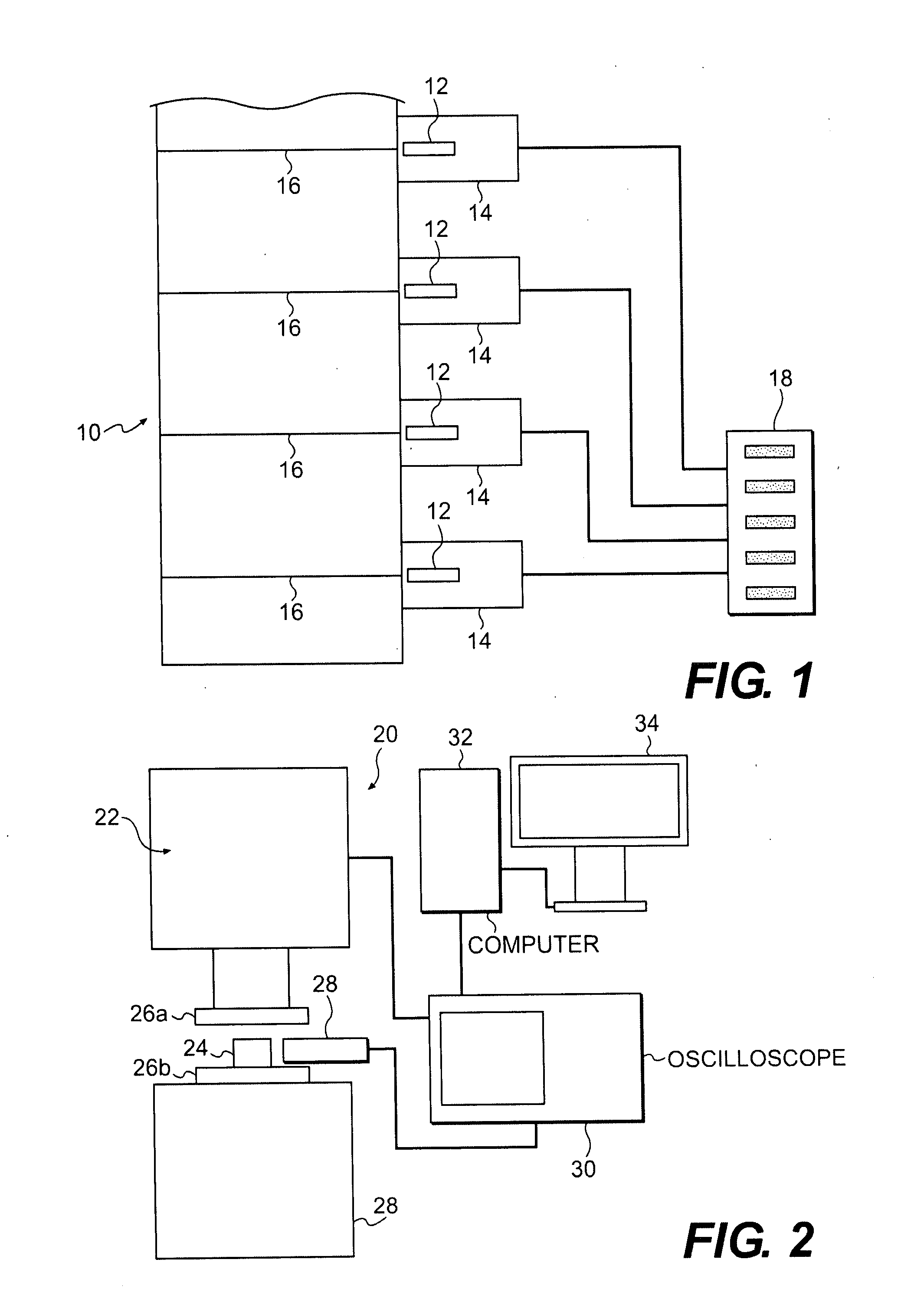
[0042]Referring to FIG. 1, there is shown a highly schematic representation of a structure 10 that is being monitored. As illustrated, a series of sensors 12, which, in one preferred embodiment, comprise conventional photomultiplier tubes (PMTs), are placed at vital areas of the structure 10, i.e., at areas, indicated at 16, where stress is most likely. It will be appreciated that while the following description makes reference to photomultiplier tubes (PMTs) other photon detectors / counters can also be used. The sensors (PMTs) 12 are housed in lightproof housings 14 so that outside light does not interfere with the measurements made by the sensors (PMTs) 12.

[0043]The outputs of each of the sensors (PMTs) 12 are connected to, or the output data from each is otherwise communicated to, a control center 18 at which technicians and / or computer programs analyze the output data to detect material fatigue and / or predict material failure. This analysis is discussed in more detail below.

[0044...


PUM

PropertyMeasurementUnit
stressaaaaaaaaaa
structural stressaaaaaaaaaa
Strengthaaaaaaaaaa

Abstract

A method and apparatus are provided for detecting strain, stress, fatigue and incipient failure in materials. A detector (e.g., a photomultiplier tube) is used to detect photonic emissions from a material under test. Data based on the detected photonic emissions is displayed in real time so as to enable real time analysis of the data in determining strain, stress, fatigue and/or incipient failure.

Description

FIELD OF THE INVENTION[0001]The present invention relates to an improved method and system for predicting material failure as well as for detecting stress and strain in materials.BACKGROUND OF THE INVENTION[0002]For years, the fields of aerospace and structural engineering have been hindered by the inability of scientists to accurately detect structural stress, to analyze the degrading effects of long-term fatigue, and, most importantly, to predict when a structure or structural member will break or fail.[0003]Particularly in the cases of advanced composites for military aircraft and aluminum engines for high performance automobiles, systematic fatigue is nearly impossible to detect (see Case, S W., and K L. Reifsnider. Fatigue of Composite Materials. Virginia Polytechnic Institute and State University. 20 Dec. 2004<http: / / www.esm.vt.edu / php / pubAbstract.php?id=10005&id_idx=8>). In this regard, there are usually no signs of material fatigue until the structure actually begins t...

Claims


Application Information

Patent Timeline
Patent Type & Authority Applications(United States)
IPC IPC(8): G01L1/24
CPCG01L1/24G01N2203/0073G01N2203/0075G01N2203/0641
Inventor WOO, GEOFFREY
Owner WOO GEOFFREY
Why Eureka
Try Eureka