Equipment and method for controlling an elevator door

a technology for elevator doors and equipment, applied in the direction of building lifts, hoisting equipment, transportation and packaging, etc., can solve the problems of large number of components, high installation cost, and large number of equipment, so as to reduce the number of separate parts, reduce the number of cabling and the amount of separate parts required, and achieve effective and versatile data transfer

Inactive Publication Date: 2008-10-02
KONE CORP
View PDF23 Cites 7 Cited by
  • Summary
  • Abstract
  • Description
  • Claims
  • Application Information

AI Technical Summary

Benefits of technology

[0012]The motor unit integrated into a coherent assembly is installed in the elevator car in the immediate vicinity of the door mechanism of the elevator. The integrated motor unit allows space and cost savings due to a substantial reduction in cabling, among other things. The assembly consisting of a control unit, motor and gear system can also be calibrated beforehand during manufacture, thus saving time during installation and maintenance of the elevator and in connection with a possible motor change.
[0014]Further according to the invention, the equipment comprises a unit for storing motor data. In this storage unit, it is possible to store e.g. characteristic data about the motor and the gear possibly associated with it, such as values of electric control parameters of the motor, information indicating the date of manufacture of the motor and gear or e.g. the highest torque sustained by the gear. These characteristic data can be read electrically into the control unit, so they can be taken into account in the control of the elevator door. A particularly significant advantage of this arrangement is that, as the motor, encoder, control unit and the storage unit containing the characteristic data are thus integrated into a single assembly, the same control system commands can be used to control several motor units of different types and consisting of different components. This allows different elevator system modules to be combined in very flexible ways when the elevator system is being designed. The storage unit may in practice be e.g. a memory element integrated in an electronics card of the control unit.
[0016]In a preferred embodiment of the invention, the data transfer bus comprises a serial communication bus. The serial communication bus can be implemented using only a two-wire cable, and thus, in addition to the data transfer function, it also allows the amount of cabling to be reduced as compared to prior-art solutions.
[0019]Integrating the button in the control system reduces cabling as well as the amount of separate parts required for door control. The button for maintenance operation of the elevator door as well as other maintenance operation buttons can be integrated e.g. directly on the electronics card in the control system portion placed on the top of the elevator car.
[0020]In the method of the invention, the characteristic data for the motor actuating the elevator door is stored in a motor data storage unit integrated in conjunction with the motor. Further according to the invention, a command for operating the elevator door is transmitted via a bi-directional data transfer bus from the elevator control system to a motor control unit integrated in conjunction with the motor, the operating command is converted in the control unit into a motor control signal corresponding to the characteristic data, operation data is generated by means of an encoder integrated in conjunction with the motor shaft and the operation data is transmitted from the control unit via the bi-directional data transfer bus to the elevator control system. The characteristic data may comprise e.g. motor performance values, information indicating the time of manufacture or e.g. the transmission ratio of a gear possibly connected to the motor and the maximum torque sustained by it. The characteristic data is preferably stored beforehand in the storage unit, e.g. already at the manufacturing stage. Thus it can be taken into account when an operating command coming from the control system is being converted into a motor control signal. As the control unit is integrated in conjunction with the motor, no separate control electronics is needed between the control system and the motor as in prior-art solutions. Together with the bi-directional data transfer bus, this allows, besides reducing the number of separate parts, more effective and versatile data transfer between the motor and the control system. From the point of view of the elevator manufacturer, the task of designing the door control system is simplified as the elevator control system can send target values related directly to door movements without having to know the properties of the various parts of the motor unit. Thus, the same operating commands can be used to control several motor units of different types. Utilizing operation data obtained from the motor, the control system can control the elevator doors in a more flexible and effective manner and more safely than before. The operation data transferred from the motor to the control system can be used to monitor e.g. the operating hours of the motor and thus to optimize the times for maintenance measures.
[0021]In an embodiment of the invention, the operating command and the operation data are transferred via a serial communication bus. A bi-directional data transfer bus can be implemented as a cable containing only two conductors, and thus the use of such a bus contributes towards reducing the amount of cabling required.

Problems solved by technology

Such an equipment is laborious and expensive to install.
Additional costs result from the large number of components.
Moreover, this solution is not optimal when the space required by the parts outside the elevator car is to be minimized.
On the other hand, in a typical system, no information regarding e.g. the floor at which the elevator is currently located can be transmitted to the control unit of the door operator motor.
Therefore, if the landing doors on different floors differ in weight, the motor torque has to be designed according to the heaviest landing door, which is not the best possible solution in respect of efficiency.
Such calibration naturally increases the installation time and causes extra costs.
In addition, each motor type requires a specific control electronics unit, which involves more complexity in the production process especially in the case of an extensive product range comprising many elevator systems of different types.
Replacing a damaged motor and control electronics unit is a laborious task and often requires re-calibration of the control electronics unit at the site of installation of the elevator.
However, this patent specification presents no solutions to the other functional shortcomings or problems referred to above.

Method used


Image

  • Equipment and method for controlling an elevator door
  • Equipment and method for controlling an elevator door
  • Equipment and method for controlling an elevator door

Examples


Embodiment Construction

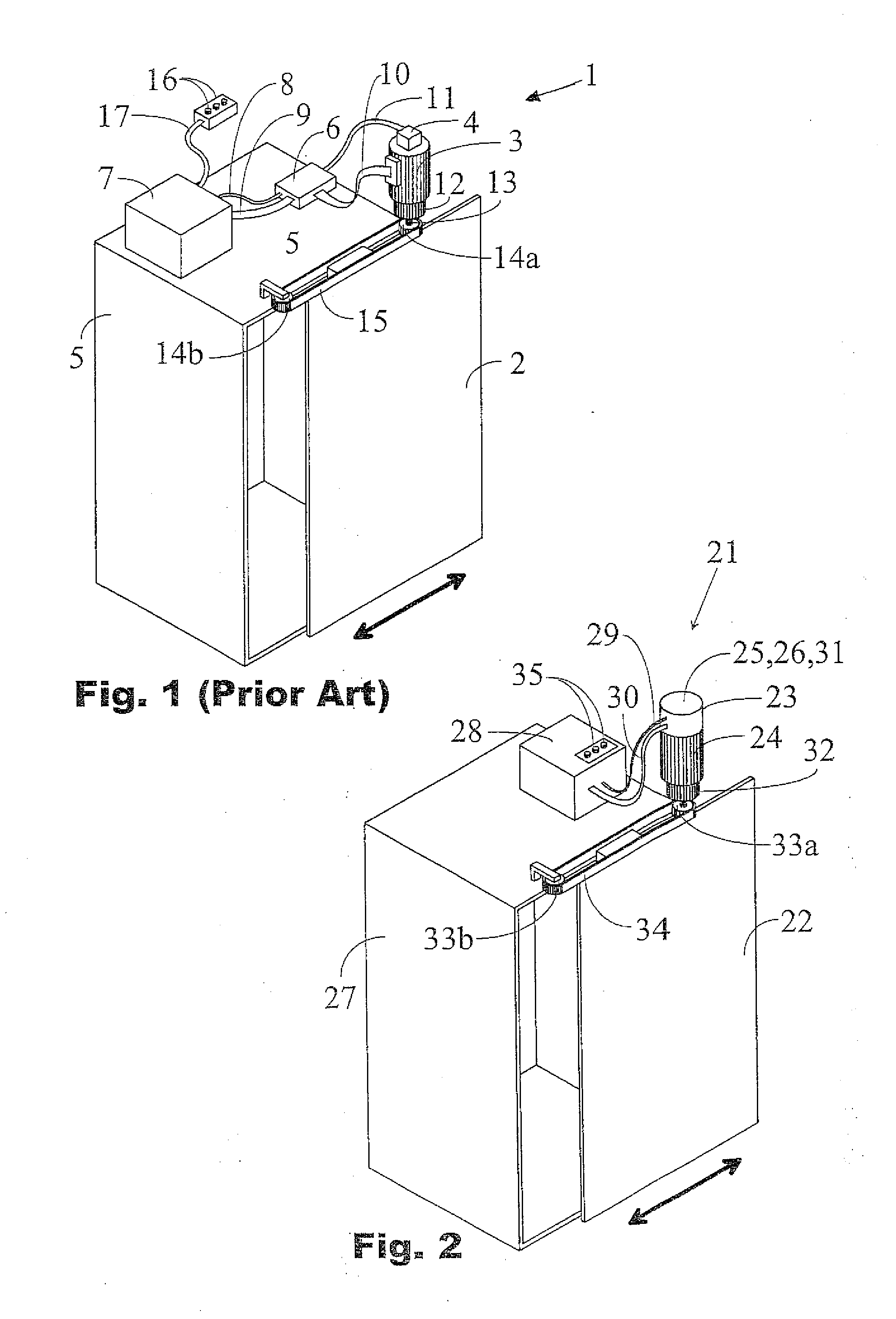
[0033]The prior-art equipment 1 for controlling an elevator door 2 as presented in FIG. 1 comprises a motor 3, an encoder 4 connected to it and a motor control electronics unit 6 placed on the top of the elevator car 5. Moreover, the equipment comprises an elevator control system portion 7 disposed on the top of the elevator car. Connected between the elevator car top portion 7 of the control system and the control electronics unit 6 is a power supply cable 8 and a serial data communication cable 9. Connected between the control unit 6 and the motor 3 is a signal cable 10 for the transmission of motor control signals. In addition, the encoder 4 is connected by a feedback cable 11 to the control electronics unit 6 for the transmission of feedback signals from the motor to the control electronics unit. Coupled to the motor is a gear 12, which has an output shaft 13 with a first cogwheel 14a mounted on it. A corresponding second cogwheel 14b is rotatably mounted on the top of the eleva...


PUM


Abstract

An equipment (21) for controlling an elevator door (22) comprises a motor (24), an encoder (25) connected to the motor and a motor control unit (26), which are integrated into a coherent motor unit (23), an elevator control system (28), power supply means (29) for supplying operating power from the control system to the motor unit, and a data transfer bus (30) for data transfer between the control system and the motor unit. According to the invention, the data transfer bus (30) is bi-directional, and the motor unit (23) comprises a motor data storage unit (31).

Description

FIELD OF THE INVENTION[0001]The present invention relates to an equipment and a method for controlling an elevator door.BACKGROUND OF THE INVENTION[0002]The elevator door which moves together with the elevator car typically consists of one or two door leaves, which are moved by a so-called door operator. An essential component of the door operator is an electric motor producing a driving force which is used to move the door leaves in a desired manner. In addition, each floor is usually provided with separate landing doors. The landing doors, too, can be moved by the door operator in such manner that the opening or closing car door leaf also engages the landing door leaf.[0003]The equipment controlling the elevator door usually additionally comprises a door control unit for controlling the door operator motor and an encoder arranged in conjunction with the motor shaft to provide feedback from the motor to the control unit. The control unit is used to control the operation of the moto...

Claims


Application Information

Patent Timeline
Patent Type & Authority Applications(United States)
IPC IPC(8): B66B13/14B66B
CPCB66B13/143B66B13/146
Inventor KATTAINEN, ARIRASANEN, MATTILAASONEN, TIMO
Owner KONE CORP
Why Eureka
Try Eureka