Apparatus and method for trapping bead based reagents within microfluidic analysis systems

a technology of microfluidic analysis and apparatus, applied in chemical microanalysis, component separation, gas generation device, etc., can solve the problems of limiting the utility of microfluidic devices, unable to be readily packed or exchanged, and unable to achieve effective utilization of microfluidic devices

Inactive Publication Date: 2008-10-02
THE GOVERNORS OF THE UNIV OF ALBERTA
View PDF99 Cites 41 Cited by
  • Summary
  • Abstract
  • Description
  • Claims
  • Application Information

AI Technical Summary

Benefits of technology

[0029]In another embodiment, the method further includes the step of providing a hook structure at the connection point between said flow channel and said trapping zone, so as to prevent direct line-of-sight entry of said packing material, thereby to promote even packing.

Problems solved by technology

While the functionality of these devices has continued to increase, one key feature that is presently lacking in these prior art devices is the ability to effectively incorporate on-chip packed reactor beds, for introduction of packing materials with immobilized reagents or stationary phases.
While a few attempts have been made to employ packed reactor beds in some prior art designs, the difficulty of packing portions of a complex microfluidic manifold with packing material (such as microscopic beads) has so far hindered the effective utilization of these reagent delivery vehicles within microfluidic devices.
However, the packing material in this prior art design could not be readily packed or exchanged, thus limiting its utility.
Current construction methods do not produce high yields of useable frits.
Furthermore, using frits produced by prior art methods of construction often leads to the formation of undesirable bubbles.
Bubbles cause discontinuity within a column, hindering solution flow and ultimately preventing separation from occurring.
The formation of bubbles, which have been observed to increase at higher voltages, also limits the amount of voltage that can be applied across the capillary, thereby limiting column length, separation efficiency, and speed of analysis.

Method used


Image

  • Apparatus and method for trapping bead based reagents within microfluidic analysis systems
  • Apparatus and method for trapping bead based reagents within microfluidic analysis systems
  • Apparatus and method for trapping bead based reagents within microfluidic analysis systems

Examples


example

[0085]To illustrate the present invention by way of example, the inventors conducted a series of experiments, which are described here.

Chip Design

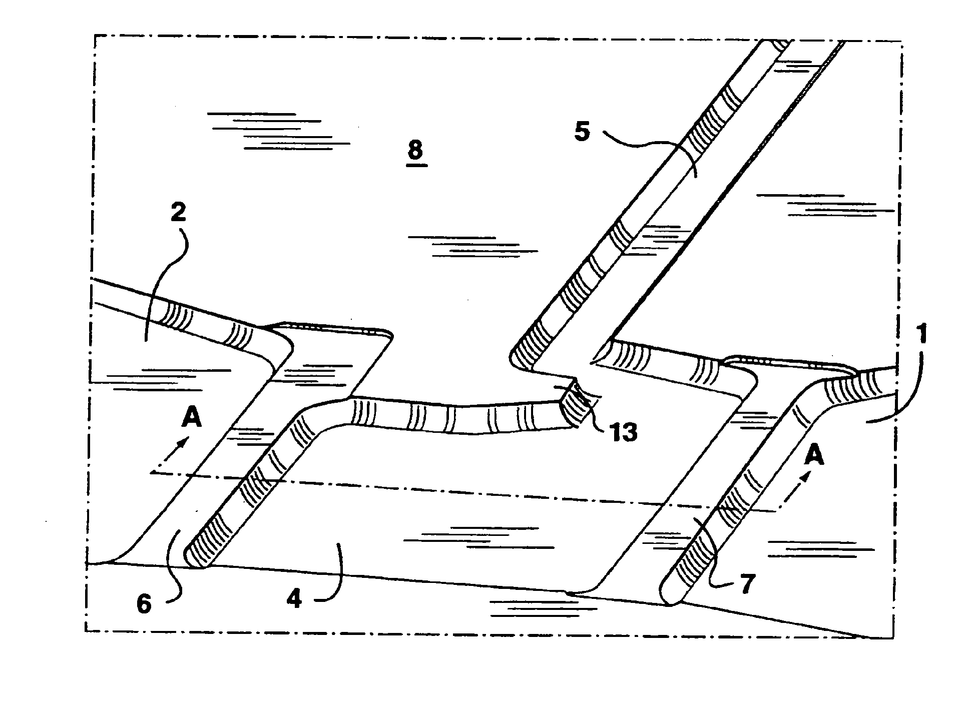
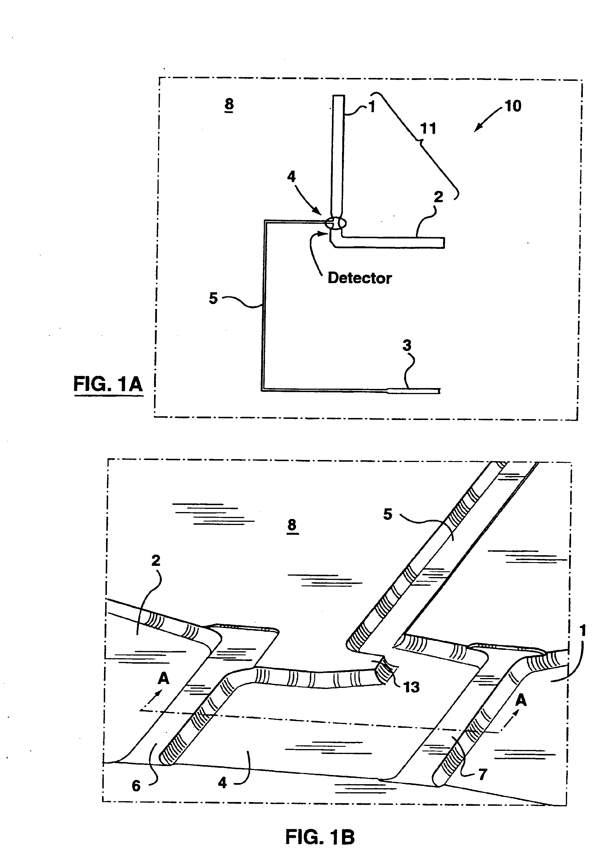
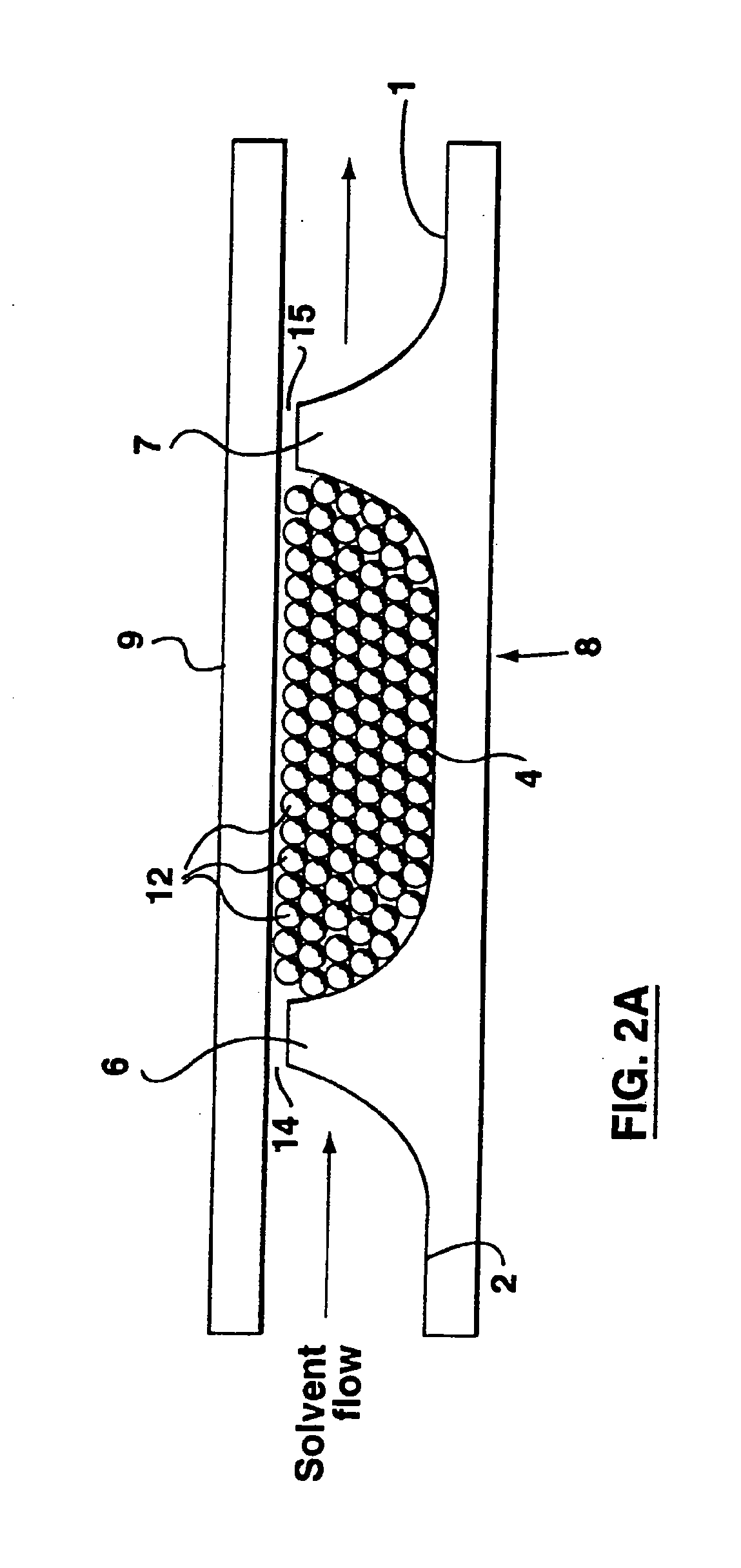
[0086]FIGS. 1A and 1B show a microfluidic device 10 as used in these experiments. The device 10 comprises a main channel 11 formed into the top surface of a substrate 8, and the main channel 11 is separated by a chamber 4, also formed into the substrate 8. Two branches of the main channel 11, as separated by the chamber 4, are further identified as main reservoirs 1 and 2. The chamber 4 is connected to a packing material reservoir 3 by a narrow side channel 5. The packing material reservoir and the narrow side channel 5 are also formed into the substrate 8. FIG. 1B shows an enlarged image of the chamber 4 obtained with a scanning electron microscope (Jeol X Vision JSM6301FXV, Peabody, Mass.). The chamber 4 is formed by providing two weirs 6, 7 formed across the main channel 11 at a relatively narrow portion of the main channel 11 (FIG. 1A)...


PUM

PropertyMeasurementUnit
diameteraaaaaaaaaa
diameteraaaaaaaaaa
path lengthaaaaaaaaaa

Abstract

An on-chip packed reactor bed design is disclosed that allows for an effective exchange of packing materials such as beads at a miniaturized level. Also disclosed is a method of treating a sample within a microfluidic analysis system, comprising: providing a main channel having a trapping zone; providing a slurry of a reagent treated packing material; inducing a flow of said packing material into said trapping zone through a flow channel connected to said trapping zone to load said trapping zone and form a packed bed of said packing material; and flowing a sample containing analytes through said packed bed, said reagent treating the sample. The present invention extends the function of microfluidic analysis systems to new applications including on-chip solid phase extraction (SPE) and on-chip capillary electrochromatography (CEC). The design can be further extended to include integrated packed bed immuno- or enzyme reactors.

Description

CROSS REFERENCE TO RELATED APPLICATIONS[0001]This is a continuation of application Ser. No. 10 / 148,425 filed Nov. 4, 2002.FIELD OF THE INVENTION[0002]The present invention relates generally to microfluidic analysis systems, and more specifically to micro-Total Analysis Systems (μ-TAS), for performing liquid phase analysis at a miniaturized level.BACKGROUND INFORMATION[0003]Recent developments in the field of micro-Total Analysis Systems (μ-TAS) have led to systems that perform chemical reactions, separation and detection at a miniaturized level on a single microchip [see, for example, Harrison, D. J.; Fluri, K.; Seiler, K.; Fan, Z.; Effenhauser, C. S.; and Manz, A., Science 1993, 261, 895-897. Harrison, D. J.; and van den Berg, E.; Eds., Micro Total Analysis Systems '98, Proceedings of the μTAS '98 Workshop (Kluwer: Dordrecht, 1998). Coyler, C. L.; Tang, T.; Chiem, N.; and Harrison, D. J., Electrophoresis 1997, 18, 1733-1741].[0004]Most prior art microfluidic devices are based on co...

Claims


Application Information

Patent Timeline
Patent Type & Authority Applications(United States)
IPC IPC(8): B01J8/00B01L3/00G01N31/20G01N1/00G01N1/10G01N1/40G01N30/28G01N30/56G01N30/60G01N35/08G01N37/00
CPCB01L3/502707Y10T436/255B01L2200/0668B01L2300/0816B01L2300/0877B01L2400/0415B01L2400/043B01L2400/0487G01N1/40G01N1/405G01N30/56G01N30/6095G01N2030/285G01N2030/565Y10T436/25Y10T436/25375Y10T436/2575B01L3/502761
Inventor HARRISON, D. JEDOLESCHUK, RICHARDSHULTZ-LOCKYEAR, LORANELLESKINNER, CAMERONLI, PAUL
Owner THE GOVERNORS OF THE UNIV OF ALBERTA
Why Eureka
Try Eureka