Dental firing furnace

a technology for firing furnaces and dentition, applied in the direction of furnace control devices, electric heating for furnaces, dental prosthetics, etc., can solve the problems of unsuitable solution, unsuitable corresponding vibration of firing materials, and unsuitable solution in principle, so as to shorten the preheating time and reduce the cycle time

Active Publication Date: 2008-10-02
IVOCLAR VIVADENT AG
View PDF4 Cites 30 Cited by
  • Summary
  • Abstract
  • Description
  • Claims
  • Application Information

AI Technical Summary

Benefits of technology

[0013]The solution according to the invention also permits compensation of the cooling that goes ahead during transfer from the preheating firing furnace into the dental firing furnace. The time in which the cooling occurs and, correspondingly, the extent of the cooling, depend, on the one hand, on the muffle size, and on the other hand on the distance between the preheating furnace and dental firing furnace and, finally, also on the rate at which the dental technician is working. According to the invention, it is particularly favorab...

Problems solved by technology

However, this solution is not suitable in principle if, apart from the quantity of material provided for melting, the temperature thereof is also different.
However, this brings about a corresponding vibration of the firing material that is not desired in some cases.
In particular, this solution is also not suitable if use is made of a press furnace since the effect of the press ram that is built into the furnace hood is to fix the site at which the muffle must be located as carrier for the firing material.
Furthermore...

Method used


Image

  • Dental firing furnace
  • Dental firing furnace
  • Dental firing furnace

Examples


Embodiment Construction

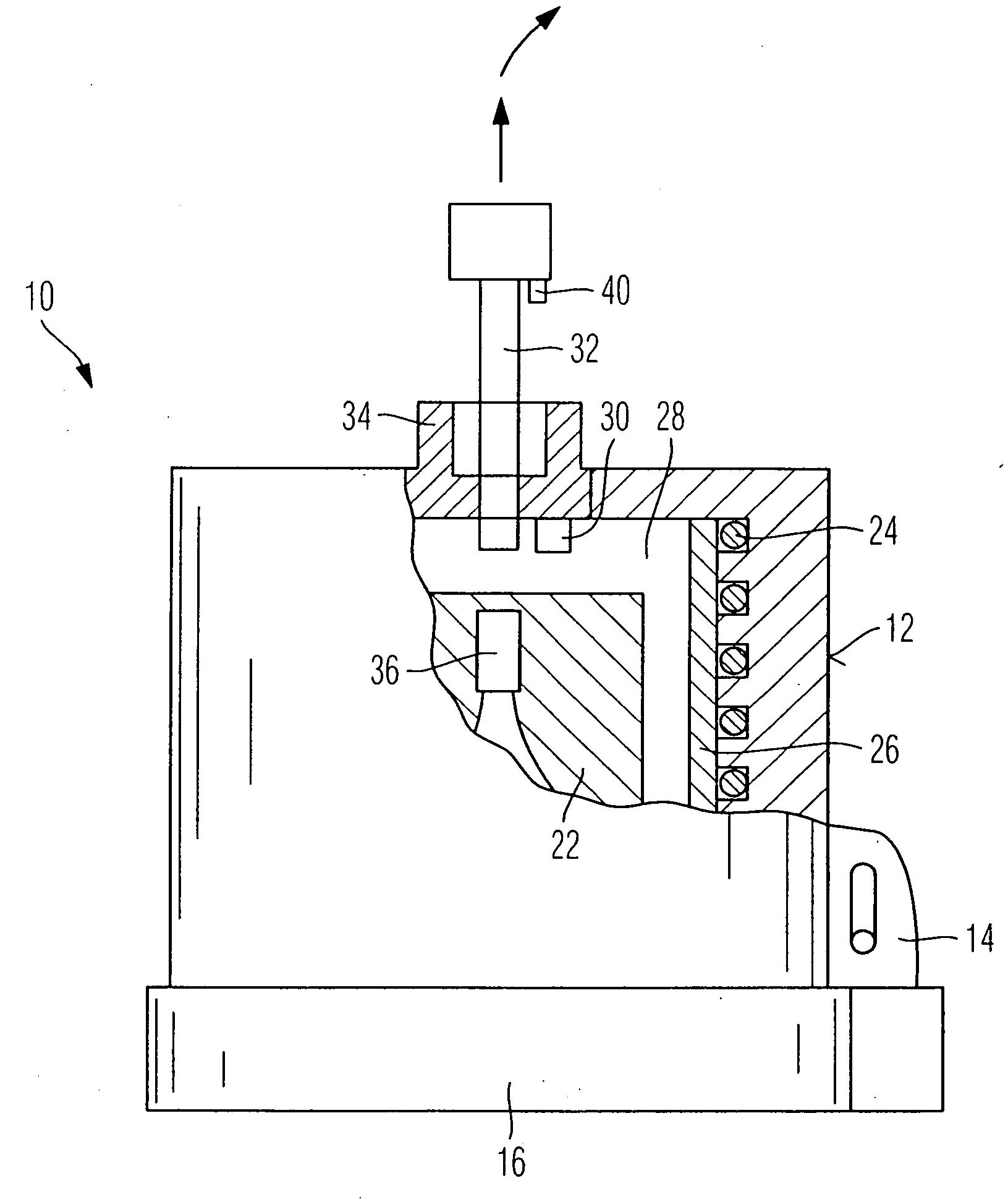
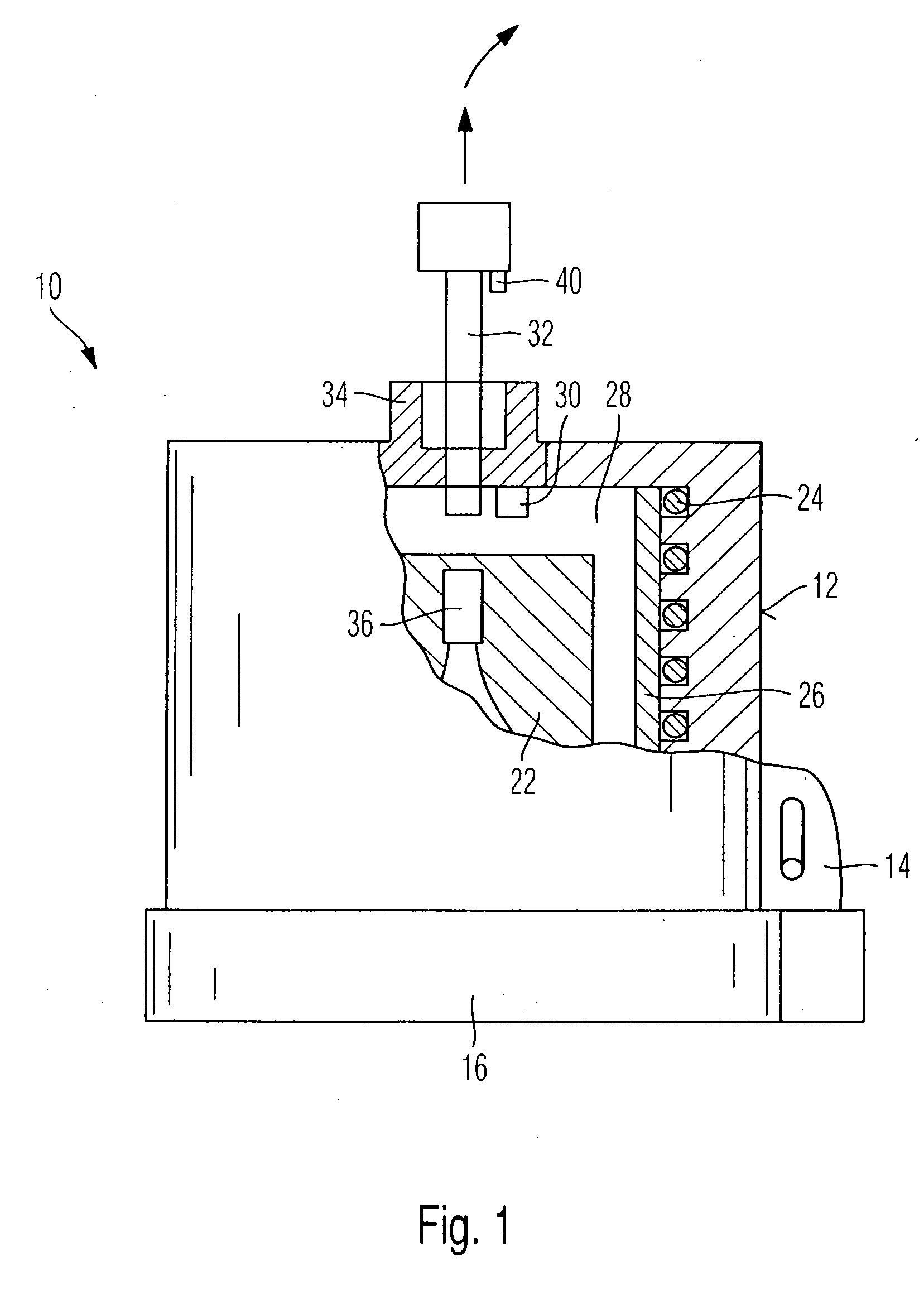
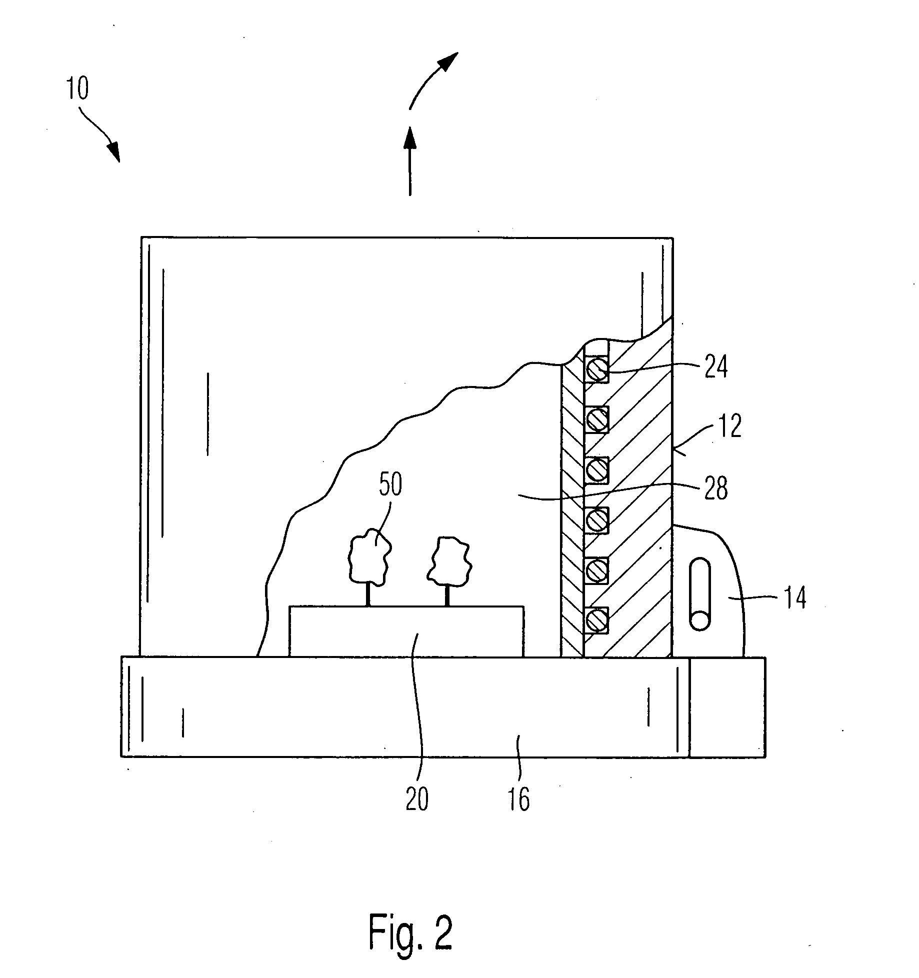
[0042]The dental firing furnace 10 illustrated in FIG. 1 has a furnace hood 12 that can be removed from a baseplate 16 in a way known per se via a joint 14. A lifting / swiveling movement such as is known per se is preferably possible. The baseplate 16 holds a carrier 20, a muffle 22 being used here as carrier.

[0043]In its side wall, the furnace hood 12 holds a heater 24 that covers a quartz tube 26. The heater 24 serves for heating a firing space 28 in which the muffle 22 is loaded.

[0044]According to the invention, a temperature sensor 30 (visible merely schematically) is provided which can be combined with a pressure sensor (not illustrated). In this embodiment, the pressure sensor detects the pressure applied to the ceramic blank 36 by a pressing device 32 via a press ram 34. A position sensor 40 that detects how the press ram 34 of the pressing device 32 moves downward is additionally provided in this embodiment.

[0045]In order to operate the dental firing furnace 10 according to t...


PUM


Abstract

The present invention relates to a dental firing furnace having a firing space and at least one carrier for dental material, in particular a muffle, which can be loaded into the firing space, and, in particular, a pressing device for pressing a ceramic blank inserted in the muffle, at least one physical variable of the firing space and/or of the carrier and/or of the muffle and/or of the ceramic blank being detected. A processing program of the dental furnace (10) that can be set is based on the detected physical variable.

Description

CROSS-REFERENCE TO RELATED APPLICATIONS[0001]This application claims foreign priority benefits under 35 U.S.C. § 119(a)-(d) from German patent application ser. no. P 10 2007 015 435.8 filed Mar. 30, 2007. In addition, this application claims the benefit under 35 U.S.C. § 119(e) of U.S. provisional patent application Ser. No. 60 / 931,580 filed May 24, 2007.TECHNICAL FIELD[0002]The invention relates to a dental firing furnace, and more particularly to a dental firing furnace provided with a firing space and a carrier for dental material which can be loaded into the firing space, and a pressing device for pressing a ceramic blank inserted in the carrier, and including a processing program which can be set on the basis of a detected physical variable.BACKGROUND OF THE INVENTION[0003]DE 33 15 835 C2 discloses a vacuum pressure casting device that uses a crucible with melt material. Via a site-mounted thermocouple, it is intended to detect temperature changes that are caused by the melt ma...

Claims


Application Information

Patent Timeline
IPC IPC(8): F27B5/10
CPCA61C13/20F27B17/025F27D19/00F27D21/00
Inventor JUSSEL, RUDOLF
Owner IVOCLAR VIVADENT AG
Why Eureka
Try Eureka