Transmission electron microscope micro-grid and method for making the same

Active Publication Date: 2008-10-02
HON HAI PRECISION IND CO LTD +1
View PDF23 Cites 55 Cited by
  • Summary
  • Abstract
  • Description
  • Claims
  • Application Information

AI Technical Summary

Problems solved by technology

However, in actual applications, the non-crystal carbon films influence the observation of the high-resolution transmissi...

Method used


Image

  • Transmission electron microscope micro-grid and method for making the same
  • Transmission electron microscope micro-grid and method for making the same
  • Transmission electron microscope micro-grid and method for making the same

Examples


Embodiment Construction

[0017]Reference will now be made to the drawings to describe, in detail, embodiments of the present TEM micro-grid and method for making the same.

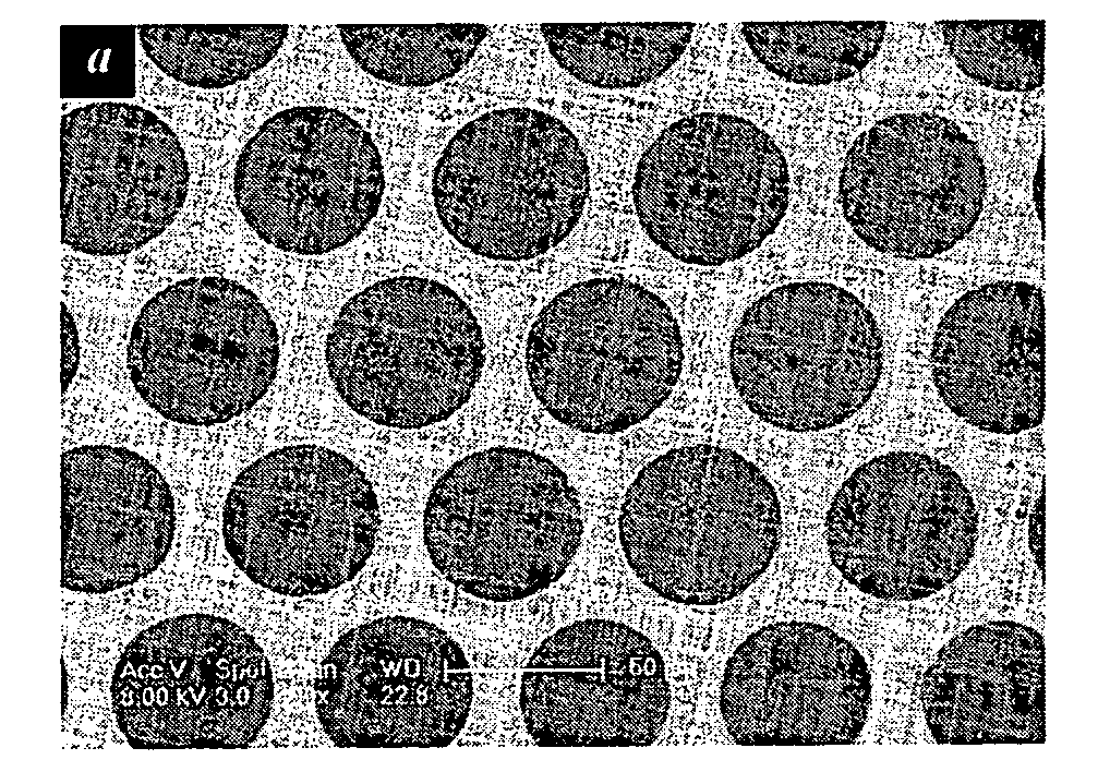
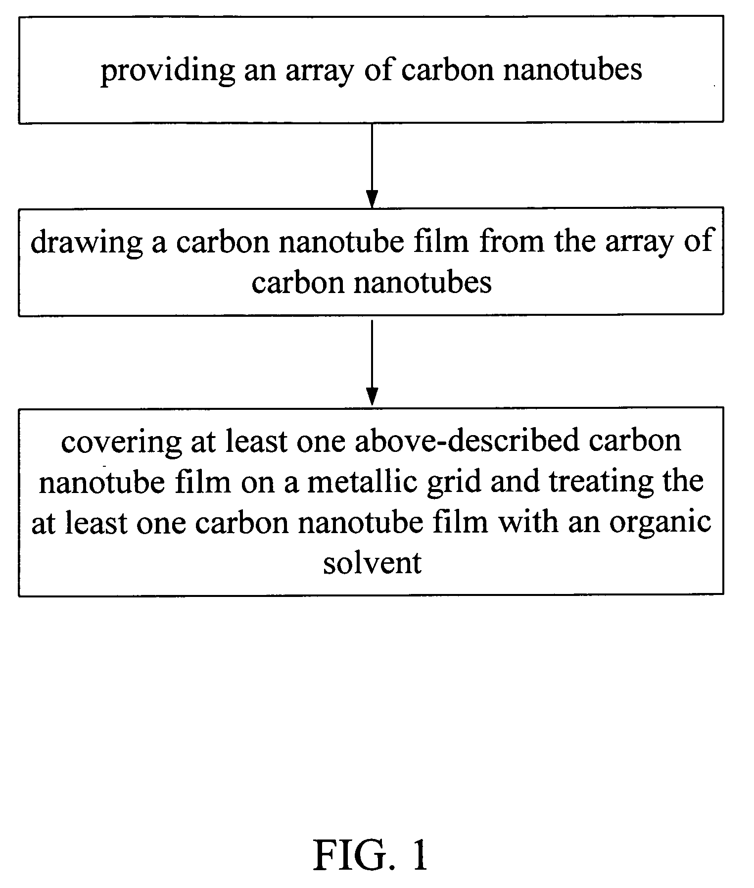
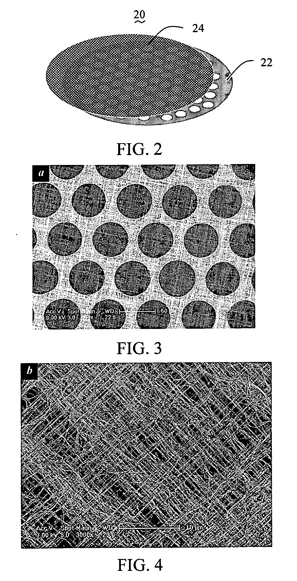
[0018]Referring to FIG. 1, a method for making a TEM micro-grid includes the steps of: (a) providing an array of carbon nanotubes, quite suitably, providing a super-aligned array of carbon nanotubes; (b) drawing a carbon nanotube film from the array of carbon nanotubes; (c) covering at least one above-described carbon nanotube film on a metallic grid, and treating the at least one carbon nanotube film with an organic solvent.

[0019]In step (a), a given super-aligned array of carbon nanotubes can be formed by the steps of: (a1) providing a substantially flat and smooth substrate; (a2) forming a catalyst layer on the substrate; (a3) annealing the substrate with the catalyst layer thereon in air at a temperature in an approximate range from 700° C. to 900° C. for about 30 to 90 minutes; (a4) heating the substrate with the catalyst layer thereo...


PUM

PropertyMeasurementUnit
Temperatureaaaaaaaaaa

Abstract

A transmission electron microscope (TEM) micro-grid includes a metallic grid and a carbon nanotube film structure covered thereon. A method for making a TEM micro-grid includes the steps of: (a) providing an array of carbon nanotubes, quite suitably, providing a super-aligned array of carbon nanotubes; (b) drawing a carbon nanotube film from the array of carbon nanotubes; (c) covering the carbon nanotube film on a metallic grid, and treating the carbon nanotube film and the metallic grid with an organic solvent.

Description

BACKGROUND[0001]1. Field of the Invention[0002]The present invention relates to a transmission electron microscope (TEM) micro-grid and a method for making the same.[0003]2. Discussion of Related Art[0004]In a transmission electron microscope (TEM), a porous carbon supporting film (i.e., micro-grid) is used, as an important tool, to carry powder samples and to observe high-resolution transmission electron microscope (HRTEM) images. With the development of nano-technology, micro-grids are increasingly coming into widespread use in the field of electron microscopy. Recently, the micro-grids used in transmission electron microscopes are usually manufactured using a layer of organic porous membrane covered on a metal mesh net, such as copper mesh net, or nickel mesh net, and subsequently a layer of non-crystal carbon films are deposited thereon via evaporation.[0005]However, in actual applications, the non-crystal carbon films influence the observation of the high-resolution transmissio...

Claims


Application Information

Patent Timeline
IPC IPC(8): H01J37/26H01S4/00
CPCH01J37/20Y10T29/49002H01J37/26
Inventor ZHANG, LI-NAFENG, CHENLIU, LIANGJIANG, KAI-LILI, QUN-QINGFAN, SHOU-SHAN
Owner HON HAI PRECISION IND CO LTD
Why Eureka
Try Eureka