

Ultra-wide band antenna and plug-and-play device using the same
a plug-and-play device and ultra-wide band technology, applied in the direction of resonant antennas, elongated active elements, radiating element structural forms, etc., can solve the problem of limiting the size of the device due to the length of the antenna, and achieve the effect of simple structure, low cost and easy manufactur
- Summary
- Abstract
- Description
- Claims
- Application Information
AI Technical Summary
Benefits of technology
Problems solved by technology
Method used
Image

Examples
first embodiment
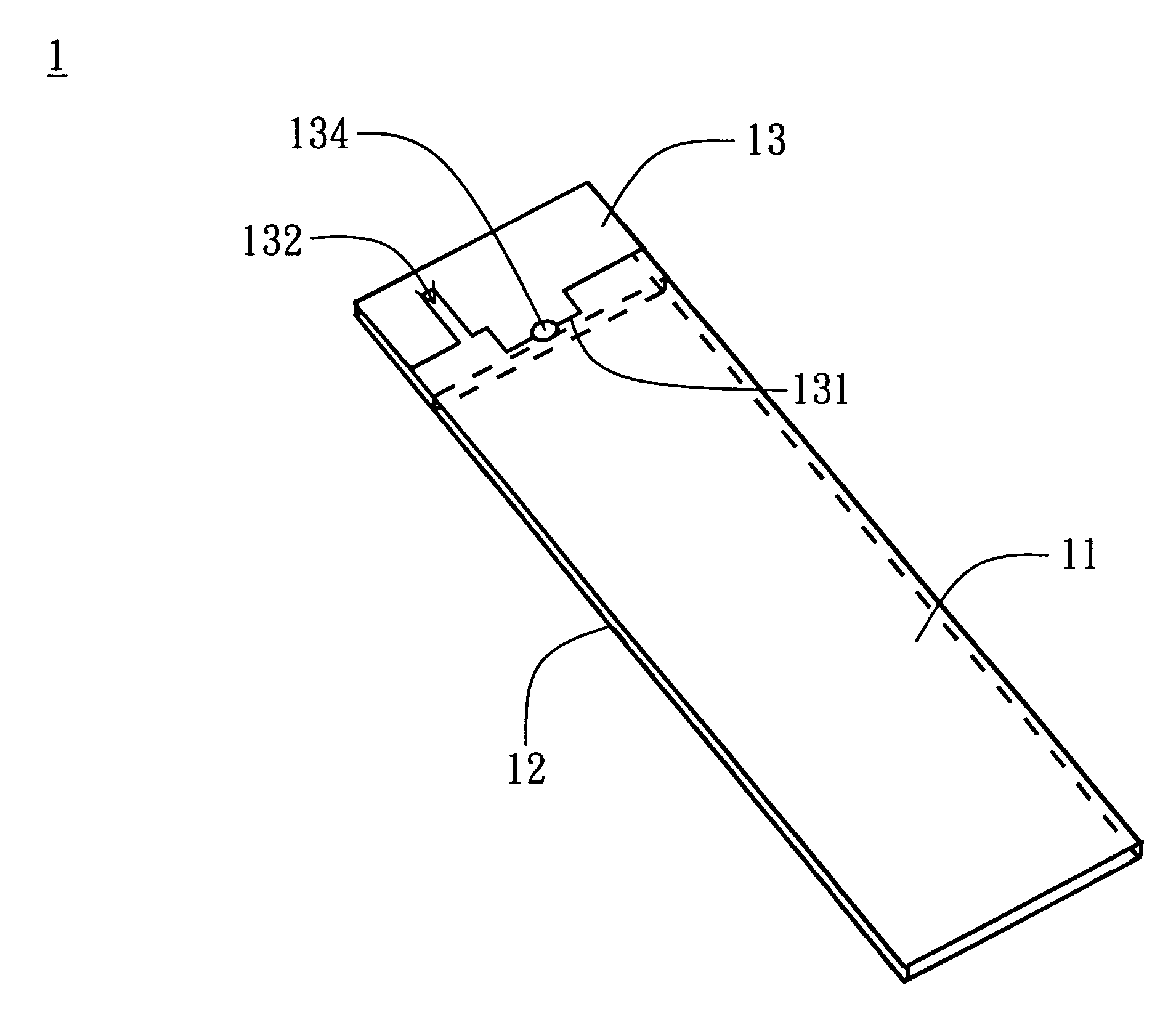
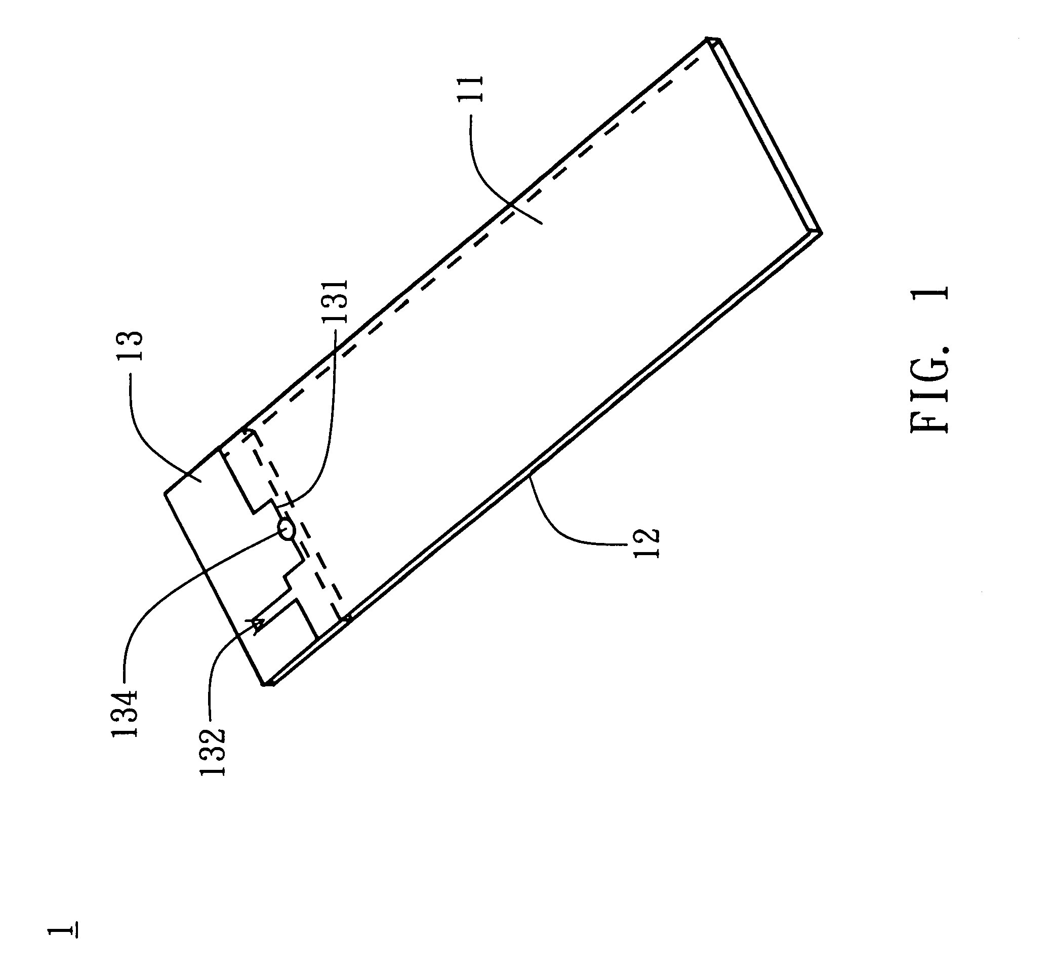
[0024]FIG. 1 illustrates an UWB antenna according to a first embodiment of the present invention. Please referring to FIG. 1, the UWB antenna 1 is disposed on a dielectric substrate 11, such as a system circuit board of a plug-and-play device. Aground plane 12 is on the dielectric substrate 11. A radiating metal plate 13 of the antenna 1 is in a non-ground region of the dielectric substrate 11. The radiating metal plate 13 is substantially rectangular and has at least one slit cut 132. An opening of the slit cut 132 is at the edge 131 of the radiating metal plate 13 facing the ground plane 12. A feeding portion 134 of the antenna 1 is also at the edge 131 of the radiating metal plate 13 facing the ground plane 12, for feeding a signal to the antenna 1. For example, the radiating metal plate 13 is formed on the dielectric substrate 11 by printing or etching.
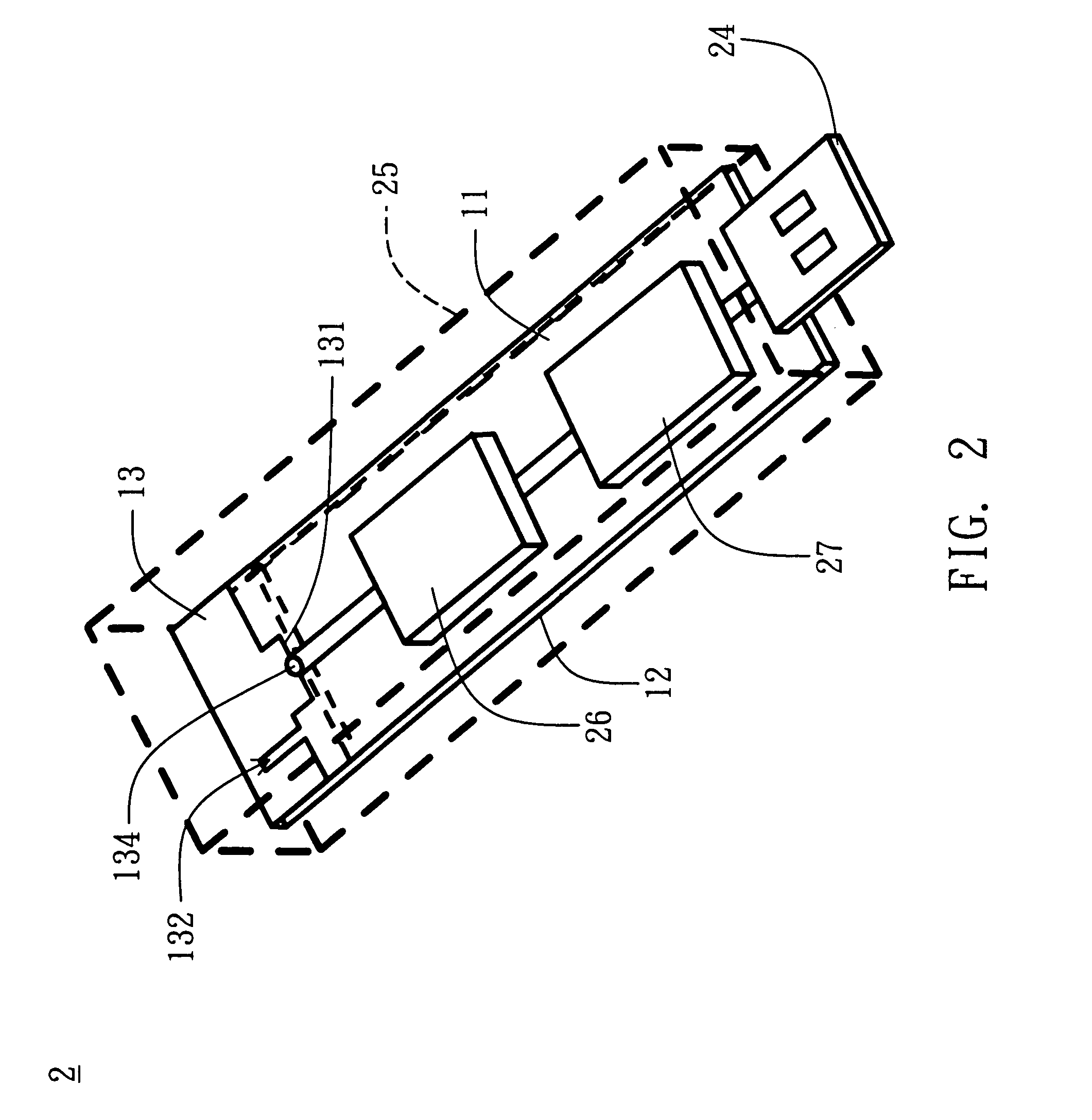
[0025]Please referring to FIG. 2, the plug-and-play device applying the UWB antenna is illustrated in FIG. 2. As shown in FIG. 2...
second embodiment
[0031]Please referring to FIG. 7, the UWB antenna according to a second embodiment of the present invention is illustrated in FIG. 7. The UWB antenna of the second embodiment and that of the first embodiment are different in the structural design of the antenna. The same components use the same reference numbers and are not described repeatedly. As shown in FIG. 7, the radiating metal plate 73 has two slit cuts 732. Preferably, the slit cuts 732 are in the non-ground region 12 and symmetric to the feeding portion 734. The slit cuts 732 are T-shaped. Although the shape of the slit cut of the present embodiment is different from that of the first embodiment, the slit cuts 732 still can increase the resonance current path of the antenna. Therefore, the size of the antenna 7 of the present embodiment is reduced.
[0032]Similarly, the opening of the slit cut 732 is at the edge 731 of the radiating metal plate 73 facing the ground plane 12. Because the current distribution is stronger here,...
third embodiment
[0033]Please referring to FIG. 8, the UWB antenna according to a third embodiment of the present invention is illustrated in FIG. 8. The UWB antenna of the third embodiment and that of the first embodiment are different in the structural design of the antenna. The same components use the same reference numbers and are not described repeatedly. As shown in FIG. 8, the slit cut 832 of the radiating metal plate 83 of the antenna 8 is inverted L-shaped. Also, a corner of the radiating metal plate 83 is cut. The opening of the slit cut 832 is at this corner and faces the ground plane 12. The feeding portion 834 of the radiating metal plate 83 is also at the edge 831. The design of the inverted L-shaped slit cut and the cut corner increase the resonance current path of the antenna. As a result, the size of the antenna of the present embodiment is reduced. Because the current distribution at the edge 831 of the ground plane 12 is stronger, the slit cut 832 formed here has significant effec...
PUM
 Abstract
Description
Claims
Application Information