Liquid crystal display having improved wavelength dispersion characteristics

a liquid crystal display and wavelength dispersion technology, applied in the field of optical compensation films, can solve the problems of color distortion due to wavelength dispersion of its proper retardation, poor image quality, and increase the dispersion in the lighted (on) sta

Active Publication Date: 2008-10-02
AKRON POLYMER SYST
View PDF25 Cites 16 Cited by
  • Summary
  • Abstract
  • Description
  • Claims
  • Application Information

AI Technical Summary

Benefits of technology

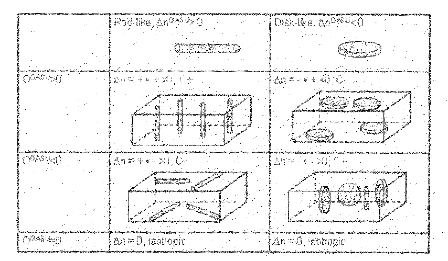
[0132]An advantage of the invention is that compensation films (positive C-plates) with high positive birefringence may be obtained by a simple solution casting process without any other post-processing such as stretching, photopolymerization, etc. Solution casting without post-processing may significantly reduce the cost of film fabrication and help eliminate errors caused by the complexity of post-processing. In certain other embodiments, post-casting processing, such as uniaxially or biaxially stretching or photopolymerization, may be used to further enhance the compensation film's high positive birefringence. The order parameter of a polymer segment, OS, is mainly determined by the conditions of solution casting, such as temperature, evaporation rate, and concentration. Thus, the conditions of solution casting impact the birefringence of the optical compensation film according to the equation Δn=ΔnOASU×OU—S×OS described above.
[0133]A variety of solvents may be used for solution casting the optical compensation films (positive C-plates) of the invention including, but not limited to, chloroform, dichloromethane, dichloroethane, benzene, chlorobenzene, xylene, N,N-dimethylformamide, N,N-dimethylacetamide, N-methyl-2-pyrrolidone, pyridine, dimethylsulfoxide, acetonitrile, cyclohexanone, methyl amyl ketone, ethyl acetate, ethylene glycol monobutyl ether, and the like. Preferred solvents include toluene, methyl isobutyl ketone (MIBK), methyl ethyl ketone (MEK), and cyclopentanone.
[0134]Optical films (positive C-plates) may be cast onto a substrate from polymer solutions by a method known in the art such as, for example, spin coating, spray coating, roll coating, curtain coating, or dip coating. Substrates are known in the art, and include TAC (triacetylcellulose), polyester, polyvinyl alcohol, cellulose ester, polycarbonate, polyacrylate, polyolefin, polyurethane, polystyrene, glass, and other materials commonly used in an LCD device.
[0135]The solution-cast compensation film (positive C-plate) may be removed from the substrate after drying to yield a free-standing film. The already high birefringence of the film may optionally be further enhanced by uniaxial or biaxial stretching. The free-standing film may also be laminated onto a substrate.
[0136]Polymer chains have a random orientation in the homogeneous solution. The conformation of polymer chains in solution is generally a random coil, unless the polymer backbone is rigid while molecular weight is low, which may have a rod-like shape. As shown in FIG. 15, polymer chains in solution resemble loosely threaded-balls filled with solvent. After solution casting, the balls deflate during solvent evaporation and collapse into flatter“pancake” shapes. This process is continuous as long as solvent evaporation continues. As a result, the order parameter of the polymer segments, Os, becomes more and more negative when the polymer collapses. Polymer chain segments become aligned parallel to the substrate surface. However, other factors such as competition between the evaporation rate of the solvent and the relaxation process of the polymer chains determine whether or not this aligned segment orientation is maintained.
[0137]When the solution for film casting is dilute, solvent evaporation generally follows a free relaxation model. During the free relaxation stage, the order parameter of the polymer segments is zero. During the free relaxation model, the system fluctuates between the collapsed ball shape and round ball shape. When the solution is dilute, the polymer's glass transition temperature is lower than the environment temperature so that polymer chains relax fast enough to compete with the collapse.

Problems solved by technology

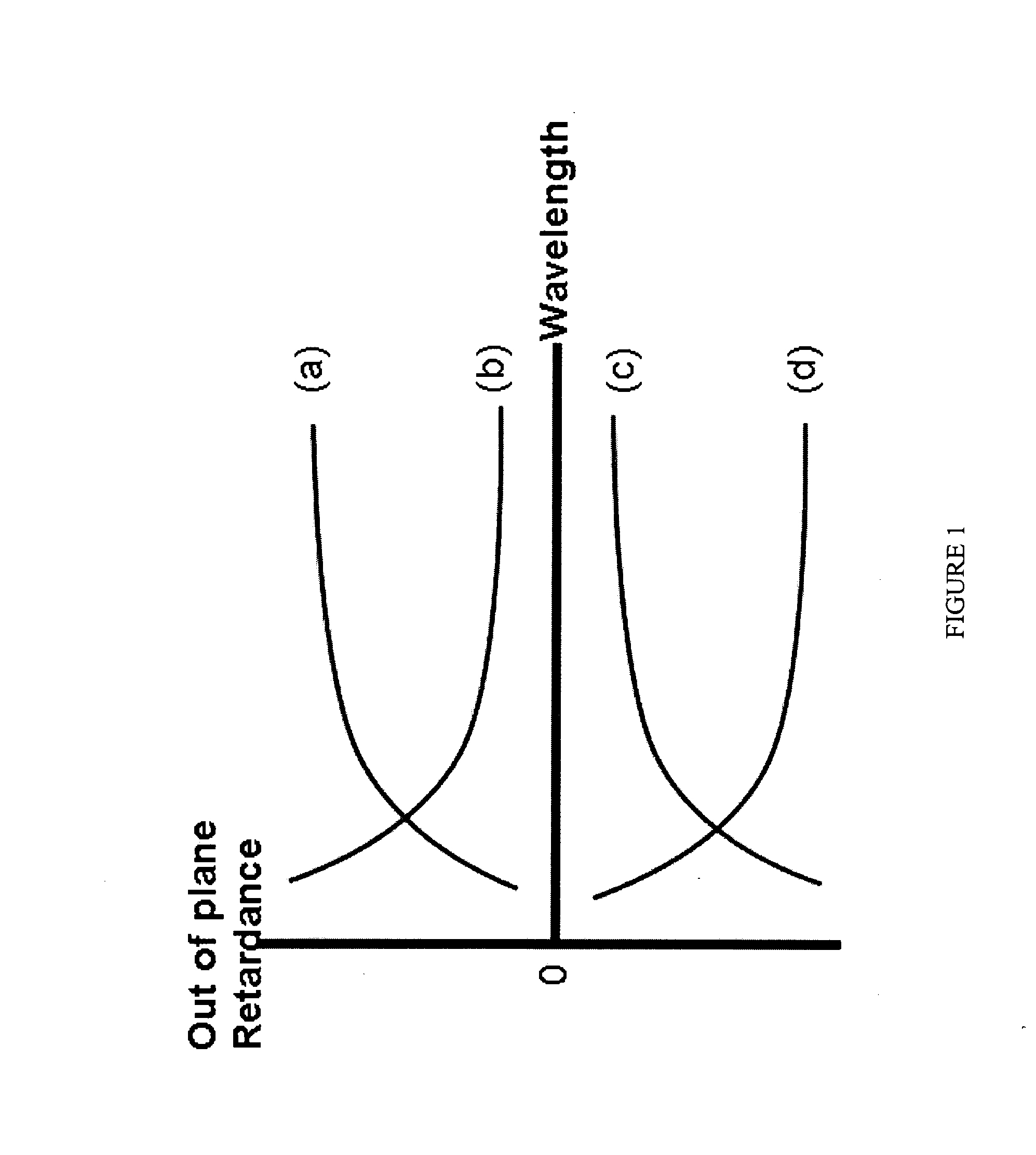
On the other hand, in the lighted (on) state, the VA-LC cell has a wavelength dispersion curve similar to a proper curve for negative retardation, which leads to color distortion due to wavelength dispersion of its proper retardation curve.
However, negative C-plates with proper wavelength dispersion do not compensate for the lighted VA-LC cell's retardation or dispersion, and, as such, color shift and poor image quality are not alleviated at those shorter wavelengths and may even increase dispersion in the lighted (on) state.
Thus, traditional negative C-plates that have a proper dispersion curve alone typically do not have the required wavelength dispersion characteristic to eliminate color shift, especially at shorter wavelengths.

Method used


Image

  • Liquid crystal display having improved wavelength dispersion characteristics
  • Liquid crystal display having improved wavelength dispersion characteristics
  • Liquid crystal display having improved wavelength dispersion characteristics

Examples


example 1

Wavelength Dispersion Curves of Various Mesogen-Jacketed Polymer Films

[0140]Mesogen-Jacketed polymers identified as PC12, PC10, PC8, and PCt having the following repeating units, respectively, were prepared:

[0141]Optical compensation films (positive C-plates) were prepared by dissolving each polymer in toluene and solution casting onto a piece of Zeonorfilm® to form coatings, as shown in FIG. 5. The coatings were allowed to dry at room temperature to form thin films with thicknesses of about 3 μm. Zeonorfilm® is a 100 μm thick substrate made of Cyclo Olifen Polymers (COP) manufactured by Zeon Chemicals, L.P. Zeonorfilm® was chosen as the substrate because it has negligible retardation throughout the wavelength range 400 nm-800 nm. The phase retardance of light passing through each film / substrate sample was measured by VASE® Ellipsometer (available from J. A. Woollam Co., Inc.). The ellipsometer was calibrated by silica every time before using. FIG. 6 shows the wavelength dispersion ...

example 2

UV Spectra of Various Mesogen-Jacketed Polymers

[0143]The following table is a collection of the absorption maximum (λmax) and the birefringence (Δn) measured at the wavelength of 633 nm for each polymer, as shown in FIG. 7.

TABLE 2Sampleλmax, nmΔn(633)PC6319.80.0355PC8319.10.0362PC10315.70.0295PC12319.80.0229PCt309.60.0184

As illustrated in Tables 1 and 2, polymers having steep slopes at shorter wavelengths generally have UV absorption maxima between 280 nm and 350 nm. Films prepared from such polymers exhibit exceptionally high positive birefringence, as shown in Table 2.

example 3

Wavelength Dispersion Curves Obtained by Stacking Polyimide Film with Mesogen-Jacketed Polymer Film

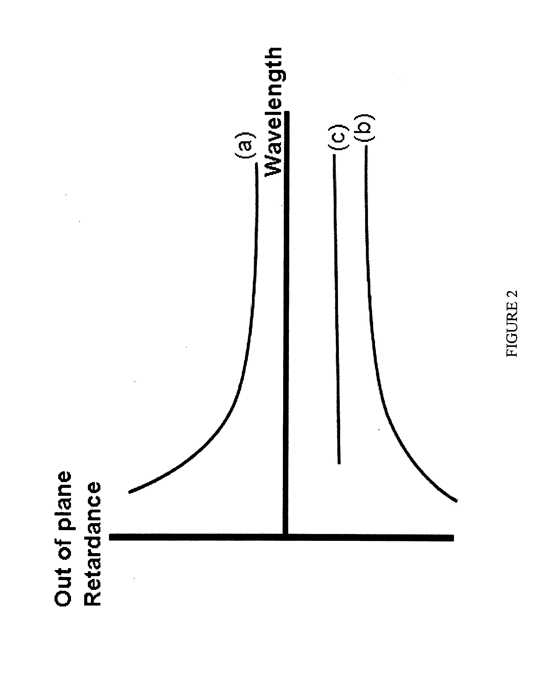
[0144]A multilayer film comprising a mesogen-jacketed polymer (PC6) film (positive C-plate) and a polyimide film APSC2 (negative C-plate) was prepared. The polyimide was dissolved in methyl isobutyl ketone (MIBK) and solution cast onto a TAC film having a thickness of 80 μm. The polyimide thickness was about 4 μm. The film was subsequently coated with a solution of mesogen-jacketed polymer, PC6, in toluene to form multilayer films with different thicknesses of the PC6 film. PC6-1 is approximately 1 μm thick; PC6-2 is approximately 2.5 μm thick; PC6-3 is approximately 3 μm thick; and PC6-4 is approximately 5 μm thick. FIG. 8 illustrates the multilayer film with PC6 as the positive C-plate. FIG. 9 shows that the out-of-plane retardation of the samples with increasing thickness of the PC6 film. The samples with the thickest positive C-plates (PC6) had an overall positive retardation. Thin...


PUM

PropertyMeasurementUnit
thicknessaaaaaaaaaa
thicknessaaaaaaaaaa
thicknessaaaaaaaaaa

Abstract

A multilayer optical retardation compensation film having at least one positive C-plate and at least one negative C-plate is used in an LCD device. The multilayer film may have a substantially flat wavelength dispersion curve, or the multilayer film combined with other layers in the LCD device may have a substantially flat wavelength dispersion curve. Polymer films for the positive C-plate may be identified according to their absorbance maxima at certain wavelength ranges.

Description

FIELD OF THE INVENTION[0001]The invention relates to optical compensation films for use in a liquid crystal display (“LCD”) devices, optical switches and waveguides where a controlled light management is desired. The LCD is more particularly a vertically-aligned-LCD (“VA-LCD”). The invention further relates to multilayer optical compensation films with reversed or substantially flat wavelength dispersion curves and LCD devices with substantially flat wavelength dispersion curves.BACKGROUND OF THE INVENTION[0002]It is known in the art of LCD compensation that the phase retardation of light varies according to wavelength (X), causing color shift. This wavelength dependence (or dispersion) characteristic of the compensation film may be taken into account when designing an LCD device so that color shift is reduced. Wavelength dispersion curves are defined as“proper” or“reversed” with respect toga compensation film with positive or negative retardance. A compensation film with positive r...

Claims


Application Information

Patent Timeline
Patent Type & Authority Applications(United States)
IPC IPC(8): C09K19/00
CPCC09K19/3842G02F1/133634Y10T428/1036G02F1/13363G02F2001/133637C09K2323/03G02F1/133637G02B5/30
Inventor HARRIS, FRANK W.JING, JIAOKAI ALEXANDERGERMROTH, TED CALVINZHENG, XIAOLIANG JOEKING, BRIAN MICHAELZHANG, DONGKUO, THAUMINGZHOU, QIFENG
Owner AKRON POLYMER SYST
Why Eureka
Try Eureka