Organic electroluminescent device

Inactive Publication Date: 2008-10-02
UDC IRELAND
View PDF8 Cites 88 Cited by
  • Summary
  • Abstract
  • Description
  • Claims
  • Application Information

AI Technical Summary

Benefits of technology

[0008]An object of an illustrative, non-limiting embodiment of the invention is to provide an organic electroluminescent device having high emiss

Problems solved by technology

As electron transporting materials for organic EL devices, aluminum complex materials of hydroxyquinoline have been used, but these materials are low in the level of the lowest triplet excited state (T1 level) and phosphorescent emission is quenched in devices using phosphorescent material, so that the increase of efficiency has been difficult.
This phenomenon is conspicuous in a case o

Method used


Image

  • Organic electroluminescent device
  • Organic electroluminescent device
  • Organic electroluminescent device

Examples


examples

[0175]The invention will be described with reference to examples, but the invention should not be construed as being restricted thereto.

[0176]Exemplified compound 1 is synthesized according to the following scheme.

(Synthesis of Intermediate A)

[0177]n-Butyl lithium (a 1.6M hexane solution) (28 ml) was put into a three-neck flask having a capacity of 500 ml, and cooled to −72° C. with a dry ice / acetone bath. A THF solution (200 ml) containing 5.1 ml of m-dibromobenzene was added dropwise over 30 minutes. Subsequently, 7.5 ml of chlorodiphenylphosphine was added dropwise to the above mixture over 20 minutes, and after the mixture was stirred at −70° C. for 30 minutes, the cooling bath was taken off, followed by stirring at room temperature for 3.5 hours. Methanol (50 ml) was added to the reaction mixture. The solvent was removed under reduced pressure, liquid phase separation was performed with ethyl acetate and water, and an oily substance obtained by washing was separated by silica g...


PUM

PropertyMeasurementUnit
Molecular strain energyaaaaaaaaaa
Glass transition temperatureaaaaaaaaaa
Energy levelaaaaaaaaaa

Abstract

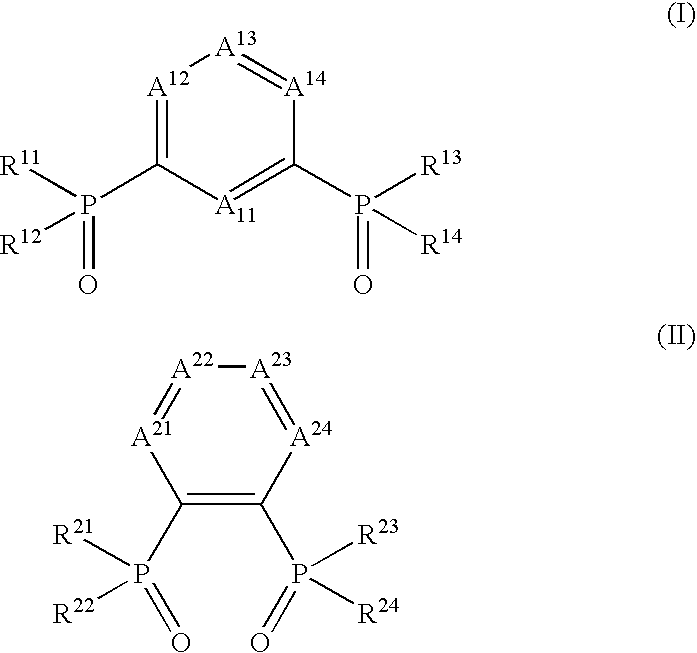
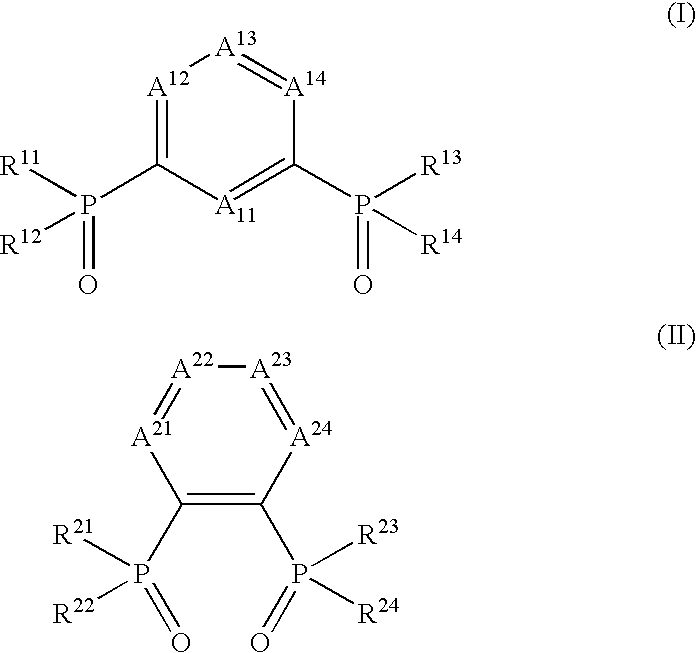
An organic electroluminescent device is provided and includes: a pair of electrodes; and an organic compound layer between the pair of electrodes, the organic compound layer including a light-emitting layer. The at least one organic compound layer contains at least one of a compound represent by formula (I) and a compound represented by formula (II).

Description

BACKGROUND OF THE INVENTION[0001]1. Field of the Invention[0002]The present invention relates to an organic electroluminescent device capable of emitting light by converting electric energy into light.[0003]2. Background Art[0004]Organic electroluminescent devices (hereinafter also referred to as “organic EL devices”) are capable of obtaining emission of high luminance by low voltage driving, and actively researched and developed. An organic electroluminescent device includes a pair of electrodes and an organic compound layer between the pair of electrodes, and electrons injected from a cathode and holes injected from an anode are recombined in the organic compound layer, and generated energy of exciton is used for light-emitting.[0005]Devices of high efficiency using phosphorescent materials are extensively developed in recent years, and light-emitting devices using iridium complexes and platinum complexes as phosphorescent materials are disclosed (for example, refer to U.S. Pat. N...

Claims


Application Information

Patent Timeline
IPC IPC(8): C09K11/00C07F1/08C07C211/54C07D209/82C07F15/00
CPCC07F9/5027C07F9/5329C07F9/587C07F9/650982C07F9/65126C07F9/65128C07F9/65216C07F9/655345C07F9/65583C07F15/0033C07F15/0086C09K11/06C09K2211/1029C09K2211/1033C09K2211/1044C09K2211/1059C09K2211/1088C09K2211/1092C09K2211/185H01L51/0067H01L51/0087H01L51/5016H01L51/5048H01L51/5096H05B33/18H05B33/20H05B33/22C07F9/58C07F9/650952C07F9/6512C07F9/6521H10K85/654H10K85/346H10K50/11H10K2101/10H10K50/14H10K50/18
Inventor FUKUNAGA, HIROFUMIISE, TOSHIHIRO
Owner UDC IRELAND
Why Eureka
Try Eureka