Continuous-atmosphere high-temperature furnace apparatus, method of continuous production of nanocarbon, and method of burning and graphitizing nano-material

a high-temperature furnace and atmosphere technology, applied in lighting and heating apparatus, furnace types, furnaces, etc., can solve the problems of inconvenient use, inconvenient control of atmosphere, and inability to meet the requirements of ultra-high-temperature ranges, so as to achieve dramatic improvement of work efficiency and reduce heating and cooling time

Inactive Publication Date: 2008-10-02
SHONAN GOSEI JUSHI SEISAKUSHO KK
View PDF4 Cites 6 Cited by
  • Summary
  • Abstract
  • Description
  • Claims
  • Application Information

AI Technical Summary

Benefits of technology

[0010]In the present invention, objects can be continuously heated by providing delivery and discharge mechanisms, an insertion mechanism, and gas supply and exhaust sections at the ends of the high-temperature furnace section. Considerable commercial and industrial advantages can be obtained in that heating and cooling time can be reduced and work efficiency can be dramatically improved in comparison with a batch-type high-temperature furnace.
[0011]The continuous-atmosphere high-temperature furnace of the present invention is also advantageous for research and development because the continuous-atmosphere high-temperature furnace makes it possible to manufacture nanocarbon as a continuous CVD apparatus and to burn and graphitize the nanocarbon thus produced.

Problems solved by technology

This is known to be inefficient because of the time required for raising and lowering the temperature.
On the other hand, there is a problem in the heat-resistance and air-tightness of the sliding areas in a continuous high-temperature furnace, and such a furnace is not suitable for controlling the atmosphere and for use in ultrahigh-temperature ranges.

Method used


Image

  • Continuous-atmosphere high-temperature furnace apparatus, method of continuous production of nanocarbon, and method of burning and graphitizing nano-material
  • Continuous-atmosphere high-temperature furnace apparatus, method of continuous production of nanocarbon, and method of burning and graphitizing nano-material
  • Continuous-atmosphere high-temperature furnace apparatus, method of continuous production of nanocarbon, and method of burning and graphitizing nano-material

Examples


embodiment 1

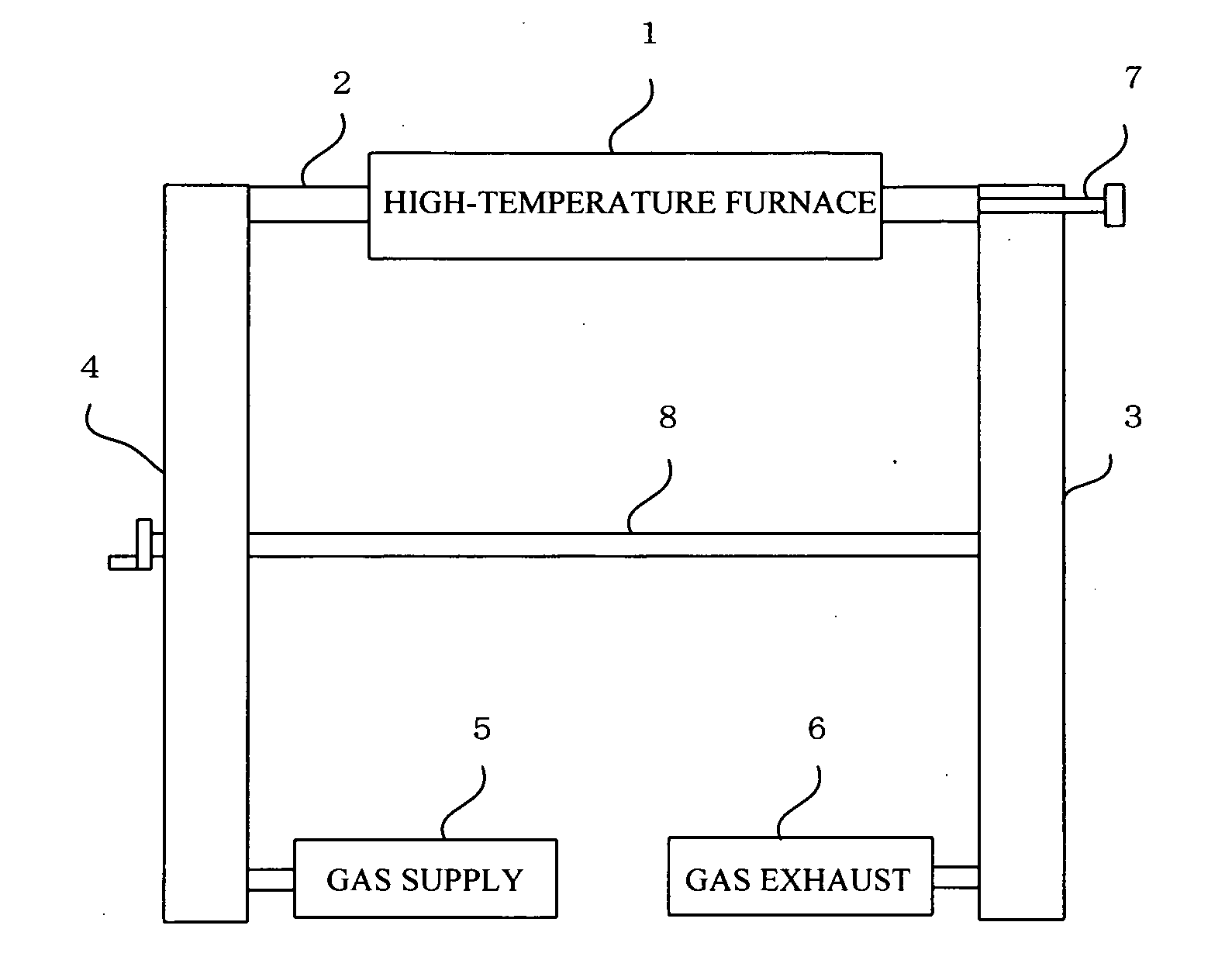
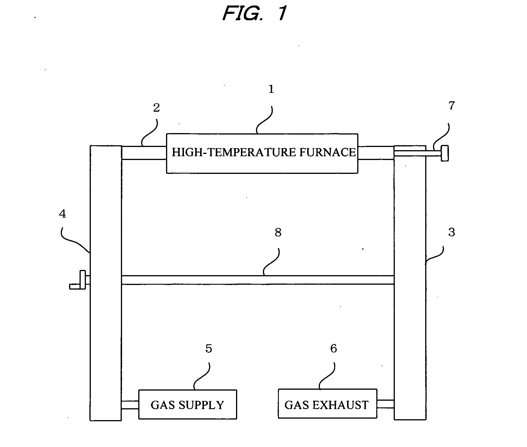
[0032]In Embodiment 1, the delivery mechanism 3 and discharge mechanism 4 are arranged as horizontally disposed belt conveyors in the same manner as the schematic diagram shown in FIG. 1. The belt conveyors are intermittently moved using a stepping motor. The insertion mechanism 7 uses a sliding rod mounted in a Wilson seal.

[0033]A mixture of iron and tin powders as a catalyst was uniformly coated onto a silicon substrate, the substrate was secured facing upward in a graphite crucible, and the crucible was placed on the conveyor of the delivery mechanism 3 from the high-temperature area.

[0034]A vacuum was formed by a vacuum pump of the gas exhaust section 6 to exhaust air from the heat-resistant tube 2, and nitrogen gas was introduced via the gas supply section 5 to the heat-resistant tube 2. These steps were carried out twice and ventilation was performed. A vacuum was formed by the vacuum pump of the gas exhaust section 6 to exhaust the nitrogen gas from the heat-resistant tube 2,...

embodiment 2

[0041]The apparatus used in Embodiment 2 was the same as in the schematic diagram shown in FIG. 1. However, the delivery mechanism 3 and discharge mechanism 4 were vertically disposed lift conveyors. The lift conveyors were intermittently moved using a stepping motor. The insertion mechanism 7 used a sliding rod mounted in a Wilson seal.

[0042]Nanocarbon produced by chemical vapor deposition (CVD) process was placed in a graphite crucible, and the crucible was placed on the conveyor of the delivery mechanism 3 from the high-temperature area.

[0043]A vacuum was formed by a vacuum pump of the gas exhaust section 6 to exhaust air from the heat-resistant tube 2, and nitrogen gas was introduced via the gas supply section 5 to the heat-resistant tube 2. These steps were carried out twice and ventilation was performed. A vacuum was formed by the vacuum pump of the gas exhaust section 6 to exhaust the nitrogen gas from the heat-resistant tube 2, and argon gas was introduced via the gas supply...

embodiment 3

[0048]The same apparatus as in Embodiment 2 was used in Embodiment 3.

[0049]Nanocarbon produced in the manner described above was placed in a graphite crucible, and the crucible was placed on the conveyor of the delivery mechanism 3 from the high-temperature area.

[0050]A vacuum was formed by a vacuum pump of the gas exhaust section 6 to exhaust air from the heat-resistant tube 2, and nitrogen gas was introduced via the gas supply section 5 to the heat-resistant tube 2. These steps were carried out twice and ventilation was performed. A vacuum was formed by the vacuum pump of the gas exhaust section 6 to exhaust the nitrogen gas from the heat-resistant tube 2, and argon gas was introduced via the gas supply section 5 to the heat-resistant tube 2.

[0051]While argon gas was introduced via the gas supply section 5, the temperature of the heat-resistant tube 2 was increased to 2800° C., and the temperature control apparatus provided to the high-temperature furnace 1 was used to automatical...


PUM


Abstract

A continuous-atmosphere high-temperature furnace apparatus comprises a high-temperature furnace section, a mechanism for continuously supplying substrates or samples to the high-temperature furnace section, and a mechanism for continuously discharging treated substrates or samples from the high-temperature furnace section. Gas is exhausted from the high-temperature furnace section and ambient gas is supplied thereto for reaction to produce carbon materials and various other nanomaterials or to burn and graphitize the nanomaterials. The substrates or samples are sequentially moved for heat treatment, thereby improving the work efficiency of the high-temperature furnace.

Description

BACKGROUND OF THE INVENTION[0001]1. Field of the Invention[0002]The present invention relates to a continuous-atmosphere high-temperature furnace apparatus comprising a mechanism for continuously feeding substrates or samples to a tubular high-temperature furnace, a mechanism for continuously discharging treated substrates or samples, and a supply and exhaust port of ambient gas; to a method of continuous production of nanocarbon and various other nanomaterials using the high-temperature furnace apparatus; and to a method of burning and graphitizing nanomaterials in which nanocarbon or various other nanomaterials are heated using the high-temperature furnace apparatus.[0003]2. Description of the Prior Art[0004]Known high-temperature furnaces include batch-type isothermal boxes, muffle furnaces, ceramic tube furnaces, continuous rotation kilns, and conveyor burning furnaces. In a batch-type high-temperature furnace, a single cycle entails increasing the burning temperature, holding t...

Claims


Application Information

Patent Timeline
Patent Type & Authority Applications(United States)
IPC IPC(8): F27D7/00F27B9/04
CPCF27B9/04F27D7/00
Inventor KAMIYAMA, TAKAOXU, GUOCHUNSHIMIZU, KAZUKI
Owner SHONAN GOSEI JUSHI SEISAKUSHO KK
Why Eureka
Try Eureka